
Nitride-based compound semiconductor light emitting device, structural unit thereof, and fabricating method thereof

a technology of compound semiconductors and light emitting devices, which is applied in the direction of semiconductor devices, electrical devices, basic electric elements, etc., can solve the problems of difficult uniform heat and pressure bonding of the entire surface of the large-area conductive substrate to the entire surface of the nitride-based compound semiconductor layer, peeling of the entire surface, and ohmic electrodes and the bonding metal layer, etc., to achieve high reliability, improve adhesion, and good yield

Active Publication Date: 2009-06-30
SHARP FUKUYAMA LASER CO LTD
View PDF37 Cites 6 Cited by
  • Summary
  • Abstract
  • Description
  • Claims
  • Application Information

AI Technical Summary

Benefits of technology

The present invention aims to improve the adhesion between a bonding metal layer and an ohmic electrode, as well as the adhesion between a conductive substrate and the ohmic electrode in a nitride-based compound semiconductor light emitting device. This will ensure a high yield and good reliability of the device. The invention includes a nitride-based compound semiconductor layer with a concave groove portion and a second bonding metal layer formed on the first ohmic electrode. The bonding process involves removing the second substrate and exposing the surface of the nitride-based compound semiconductor layer, followed by the formation of a transparent electrode. The invention also provides a fabricating method for the nitride-based compound semiconductor light emitting device.

Problems solved by technology

With such a technique, however, it was difficult to uniformly heat and pressure bond the entire surface of the large-area conductive substrate to the entire surface of the nitride-based compound semiconductor layer via the ohmic electrode and the bonding metal layer.
Thus, adhesion between the conductive substrate and the nitride-based compound semiconductor layer was poor, resulting in peeling of the entire surfaces thereof.
Further, the conductive substrate would peel off from the ohmic electrode due to poor adhesion therebetween.
If the conductive substrate and the ohmic electrode are separated from each other completely, it is not possible to remove a sapphire substrate, hindering formation of a light emitting device.
If they are partially separated from each other, flow of the current from the gallium nitride-based semiconductor layer to the conductive substrate will be difficult, leading to an increase of operating voltage, thereby causing degradation in reliability of the light emitting device.
Further, if partial peeling occurs, the support substrate may be separated from the nitride-based compound semiconductor layer upon cutting of the wafer into chips, leading to degradation in yield of the fabrication process.
Still further, the partially peeled-off state will cause penetration of solvent, resist, or etchant during the process.
For example, upon fabrication of a lamp light emitting device, resin, water or the like will enter through the peeled-off part, which will expand the peeling, possibly destroying the ohmic electrode and the bonding metal layer.
This would degrade reliability of the light emitting device.
Still further, when Au wire is bonded to a pad electrode, if adhesion between the conductive substrate and the ohmic electrode formed thereon is poor, there will occur peeling of the conductive substrate from the ohmic. electrode, thereby causing an increase of operating voltage.

Method used


Image

  • Nitride-based compound semiconductor light emitting device, structural unit thereof, and fabricating method thereof
  • Nitride-based compound semiconductor light emitting device, structural unit thereof, and fabricating method thereof
  • Nitride-based compound semiconductor light emitting device, structural unit thereof, and fabricating method thereof

Examples


example 1

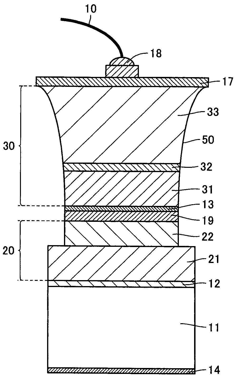
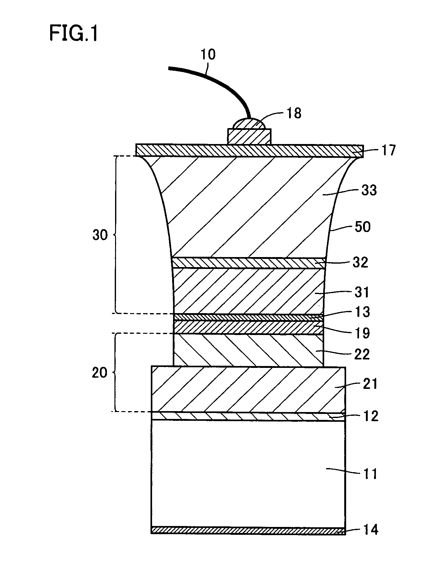
[0072]In the present example, a nitride-based compound semiconductor light emitting device as shown in FIG. 1 was formed, as will be explained in detail below.

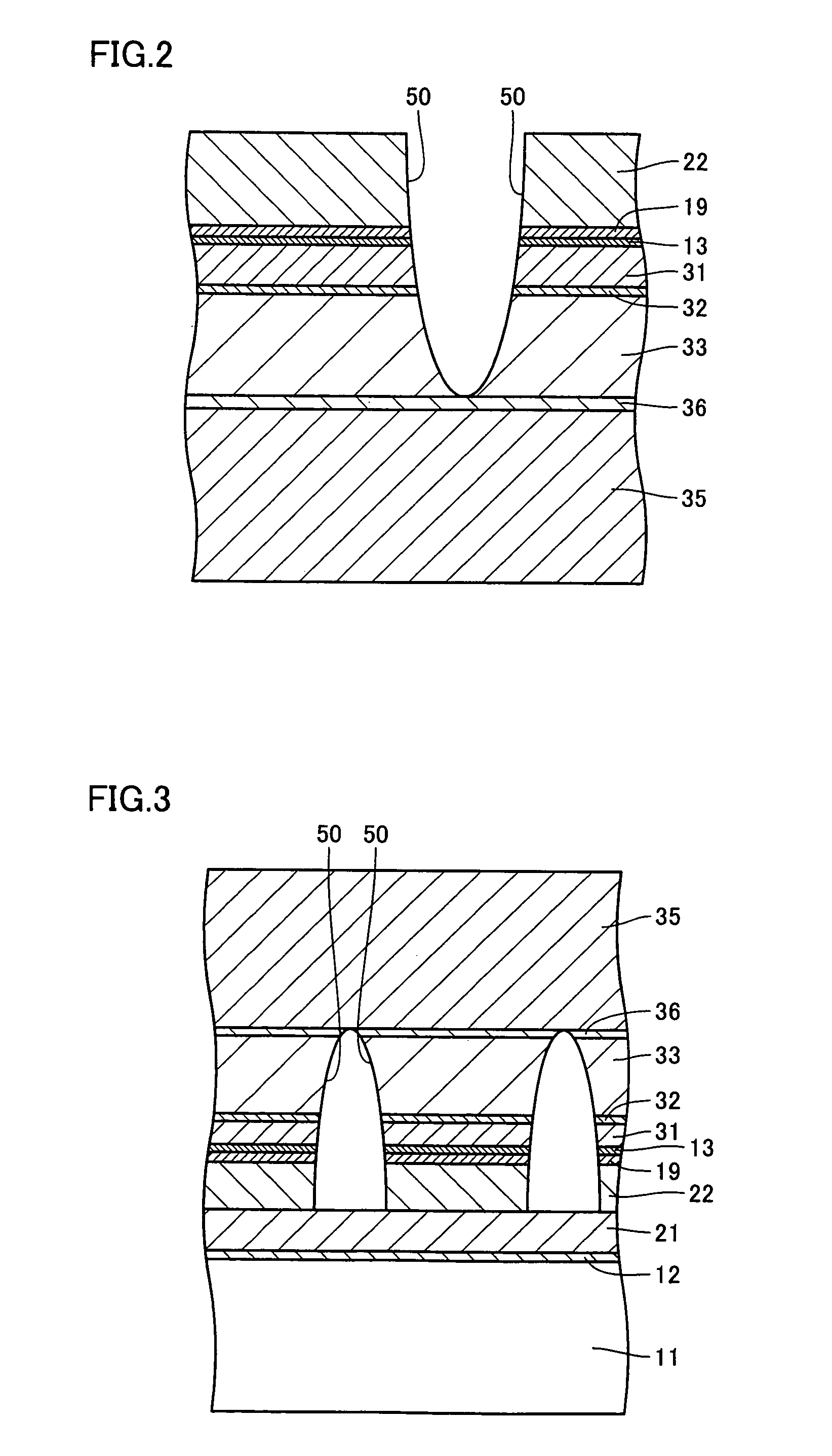
[0073]On a sapphire substrate serving as second substrate 35, a buffer layer 36 made of a GaN material, an N-type nitride-based compound semiconductor layer 33, a multi-quantum well (MQW) light emitting layer 32, and a P-type nitride-based compound semiconductor layer 31 were formed successively by MOCVD. Specifically, GaN buffer layer 36 was formed to a thickness of 20 nm, N-type nitride-based compound semiconductor layer 33 was formed to a thickness of 5 μm, MQW light emitting layer 32 was formed to a thickness of 50 nm, and P-type nitride-based compound semiconductor layer 31 was formed to a thickness of 150 nm.

[0074]Next, a concave groove portion 50 was formed in the nitride-based compound semiconductor layer formed on the sapphire substrate. RIE was employed at this time. The width of the concave groove portion was set to...

example 2

[0082]In the present example, a nitride-based compound semiconductor light emitting device as shown in FIG. 6 was fabricated, as described in detail in the following.

[0083]On a sapphire substrate serving as second substrate 35, a buffer layer 36 made of a GaN material, an N-type nitride-based compound semiconductor layer 33, a MQW light emitting layer 32, and a P-type nitride-based compound semiconductor layer 31 were formed successively, by MOCVD. Specifically, on the sapphire substrate, GaN buffer layer 36 was formed to a thickness of 30 nm, N-type nitride-based compound semiconductor layer 33 was formed thereon to a thickness of 5 μm, MQW light emitting layer 32 was formed thereon to a thickness of 50 nm, and P-type nitride-based compound semiconductor layer 31 was formed thereon to a thickness of 200 nm.

[0084]Next, a concave groove portion 50 was formed in the nitride-based compound semiconductor layer on the sapphire substrate, using RIE. The concave groove portion was made in ...


PUM

PropertyMeasurementUnit
resistivityaaaaaaaaaa

Abstract

A nitride-based compound semiconductor light emitting device includes a first conductive substrate, a first ohmic electrode formed on the first conductive substrate, a bonding metal layer formed on the first ohmic electrode, a second ohmic electrode formed on the bonding metal layer, and a nitride-based compound semiconductor layer formed on the second ohmic electrode. The nitride-based compound semiconductor layer includes at least a P-type layer, a light emitting layer and an N-type layer, and has a concave groove portion or a concave-shaped portion.

Description

[0001]This nonprovisional application is based on Japanese Patent Application No. 2004-255953 filed with the Japan Patent Office on Sep. 2, 2004, the entire contents of which are hereby incorporated by reference.BACKGROUND OF THE INVENTION[0002]1. Field of the Invention[0003]The present invention relates to a nitride-based compound semiconductor light emitting device capable of emitting light in the red to ultraviolet range, a structural unit thereof, and a fabricating method thereof. More particularly, the present invention relates to a nitride-based compound semiconductor light emitting device having a conductive substrate bonded thereto and having a concave groove portion, a structural unit thereof, and a fabricating method thereof.[0004]2. Description of the Background Art[0005]A nitride-based compound semiconductor, represented by InxGayAlzN (x+y+z=1, 0≦x<1, 0<y≦1, 0≦z<1), for example, has a large energy bandgap and high thermal stability, and allows control of the ban...

Claims


Application Information

Patent Timeline
Patent Type & Authority Patents(United States)
IPC IPC(8): H01L33/00H01L33/12H01L33/32H01L33/42
CPCH01L33/20H01L33/32H01L2224/48463
Inventor HATA, TOSHIO
Owner SHARP FUKUYAMA LASER CO LTD
Learn More