Laminate-type piezoelectric element and method of producing the same

a piezoelectric element and laminate technology, applied in the direction of generator/motor, machine/engine, mechanical apparatus, etc., can solve the problems poor conduction, stress between, etc., to suppress the occurrence of cracks in the electrically conductive adhesive, reduce the occurrence of problems, and relax stress

Inactive Publication Date: 2009-06-30
DENSO CORP
View PDF11 Cites 52 Cited by
  • Summary
  • Abstract
  • Description
  • Claims
  • Application Information

AI Technical Summary

Benefits of technology

[0008]The present invention was accomplished in view of the above problems inherent in the prior art, and provides a laminate-type piezoelectric element featuring excellent durability and reliability and a method of producing the same.

Problems solved by technology

When the laminate-type piezoelectric element is used, for example, for an injector, a variety of problems arise in severe environments, such as being used for extended periods of time in a high-temperature atmosphere.
When the stress is repetitively exerted, a problem arises in that cracks develop in the electrically conductive adhesive.
Therefore, electric conduction (hereinafter simply referred to as conduction) is not maintained between the inner electrode layers and the outer electrodes which are electrically conductive to each other via the electrically conductive adhesive, and problems such as poor conduction may arise.
Therefore, when the piezoelectric element is driven, stress occurs between any of these two elements which are in contact, and cracks occur in the electrically conductive adhesive.
That is, in the conventional structure, the effect of relaxing the stress that occurs in the electrically conductive adhesive when the piezoelectric element was being driven, and of suppressing the occurrence of cracks was not sufficient.

Method used


Image

  • Laminate-type piezoelectric element and method of producing the same
  • Laminate-type piezoelectric element and method of producing the same
  • Laminate-type piezoelectric element and method of producing the same

Examples


example 1

[0058]A laminate-type piezoelectric element according to an Example of the invention and a method of its production will be described below with reference to FIGS. 1 to 8d.

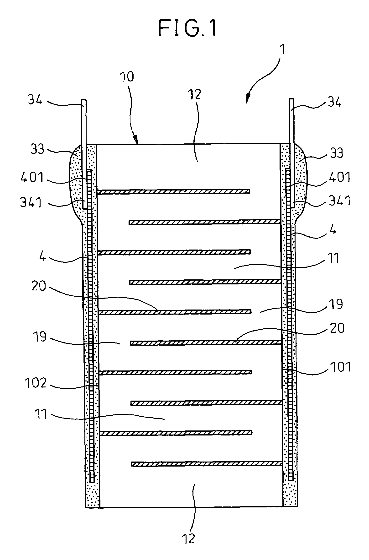
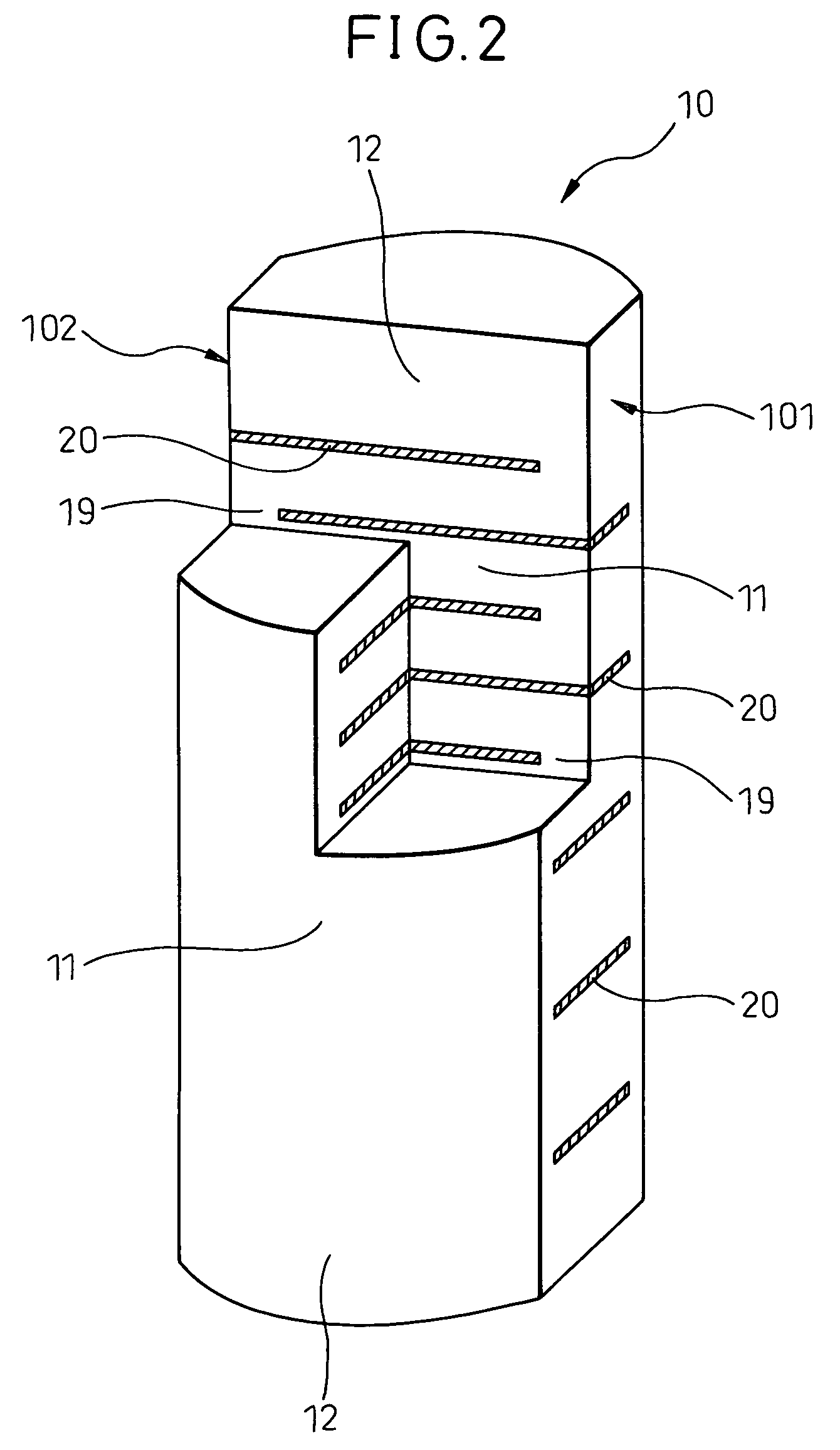
[0059]The laminate-type piezoelectric element 1 of this Example has, as shown in FIG. 1, a ceramic laminated body 10 obtained by alternately laminating piezoelectric layers 11 made of a piezoelectric material and inner electrode layers 20 having electrical conductivity, and has outer electrodes 34 joined to the side surfaces 101 and 102 of the ceramic laminated body 10 via an electrically conductive adhesive 33.

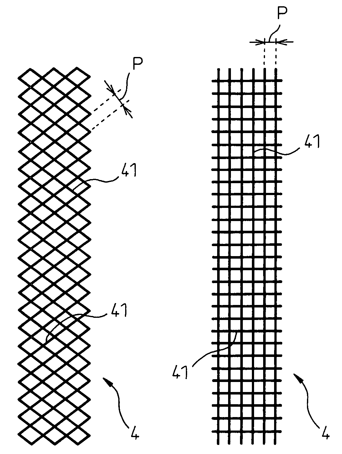
[0060]The electrically conductive adhesive 33 has buried therein mesh bodies 4 obtained by forming a mesh by using a nonmetallic material.

[0061]This Example will now be described in detail.

[0062]In the laminate-type piezoelectric element 1 of this Example, the ceramic laminated body 10 has, as shown in FIG. 2, the shape of a barrel in cross section with a pair of opposing side surfaces 101 and 102 on the o...

example 2

[0122]In this Example, the laminate-type piezoelectric element 1 of Example 1 is used as a piezoelectric actuator for an injector.

[0123]The injector 6 of this Example is applied to a common rail injection system of a diesel engine as shown in FIG. 9.

[0124]As shown in FIG. 9, the injector 6 has an upper housing 62 accommodating the laminate-type piezoelectric element 1 as a driving part, and a lower housing 63 fixed to the lower end thereof and in which an injection nozzle portion 64 is formed.

[0125]The upper housing 62 is of nearly cylindrical shape, and has the laminate-type piezoelectric element 1 inserted and fixed in a longitudinal hole 621 which deviates from the center axis

[0126]By the side of the longitudinal hole 621, a high-pressure fuel passage 622 is provided in parallel, and an upper end thereof communicates with a common rail (not shown) through a fuel introduction pipe 623 that protrudes at an upper side portion of the upper housing 62.

[0127]A fuel outflow pipe 625 pro...


PUM

PropertyMeasurementUnit
diameteraaaaaaaaaa
diameteraaaaaaaaaa
diameteraaaaaaaaaa

Abstract

A laminate-type piezoelectric element has a ceramic laminated body obtained by alternately laminating piezoelectric layers made of a piezoelectric material and inner electrode layers having electrical conductivity. Outer electrodes are joined to side surfaces of the ceramic laminated body via an electrically conductive adhesive. The electrically conductive adhesive has buried therein mesh bodies obtained by forming a mesh by using a nonmetallic material. The mesh bodies are desirably constituted by using any one of a resin, ceramic, carbon or glass.

Description

TECHNICAL FIELD[0001]The present invention relates to a laminate-type piezoelectric element applied to, for example, a piezoelectric actuator and the like and to a method of producing the same.BACKGROUND ART[0002]In recent years, injectors for fuel injection for automobiles using laminate-type piezoelectric elements have been developed from the standpoint of improving fuel efficiency of automobiles and from the environmental point of view, such as reduced exhaust gas emission.[0003]The laminate-type piezoelectric element has a ceramic laminated body obtained by alternately laminating piezoelectric layers usually made of a piezoelectric material and inner electrode layers having electrical conductivity, and has outer electrodes joined to the side surfaces of the ceramic laminated body via an electrically conductive adhesive. When a voltage is applied across the inner electrode layers, the piezoelectric layers undergo a displacement so as to be driven.[0004]When the laminate-type piez...

Claims


Application Information

Patent Timeline
Patent Type & Authority Patents(United States)
IPC IPC(8): H01L41/047F02M51/06H01L41/083H01L41/22H01L41/293H02N2/00
CPCH01L41/0472H01L41/0833H01L41/293F02M63/0026H10N30/872H10N30/503H10N30/063
Inventor KADOTANI, SHIGEIWASE, AKIOYAMAGUCHI, TERUAKI
Owner DENSO CORP
Why Eureka
Try Eureka