
Lightning damage protection for composite aircraft

a composite aircraft and damage protection technology, applied in the direction of aircraft static dischargers, emergency protective arrangements for limiting excess voltage/current, electrostatic charges, etc., can solve the problems of increasing complexity and expense, severe structural damage to unprotected composite structures and their contents, and increasing weight, etc., to achieve simple and less expensive implementation, light weight

Active Publication Date: 2009-06-30
THE BOEING CO
View PDF17 Cites 37 Cited by
  • Summary
  • Abstract
  • Description
  • Claims
  • Application Information

AI Technical Summary

Benefits of technology

The present invention provides a lightning protection system for composite-body aircraft that is lighter, simpler, and less expensive than conventional systems. The system includes a continuous, electrically conductive grid formed on the exterior surface of the aircraft body, which provides multiple secondary points for lightning strikes to attach and detach from the body, while conductive paths on the surface of the body allow the electrical current of the lightning strike to flow without causing damage. The system can be used in blended-wing-body aircraft and as a ground return path of the aircraft's electrical system.

Problems solved by technology

These strikes can cause severe structural damage to unprotected composite structures and their contents, as compared to conventional aluminum aircraft structures, because the energy of the strike cannot be efficiently conducted through the composite material without damage, due to its relatively lower thermal and electrical conductivities.
The latter are characterized by a fast-rising current having the same frequency spectrum, but with 1×10⁵ amp peaks and energy transfer densities of 0.25×10⁶ amp2 sec, and can also result in severe structural damage to unprotected composite structures.
While these systems do provide some measure of protection against damage occasioned by lightning strikes, they do so at the cost of increased complexity and expense, increased weight, and / or a reduced structural integrity of the composite material.
For example, a lighting protection system that relies on metal-plated graphite fibers both substantially increases the weight, and decreases the strength of the resulting composite structure.

Method used


Image

  • Lightning damage protection for composite aircraft
  • Lightning damage protection for composite aircraft
  • Lightning damage protection for composite aircraft

Examples


Embodiment Construction

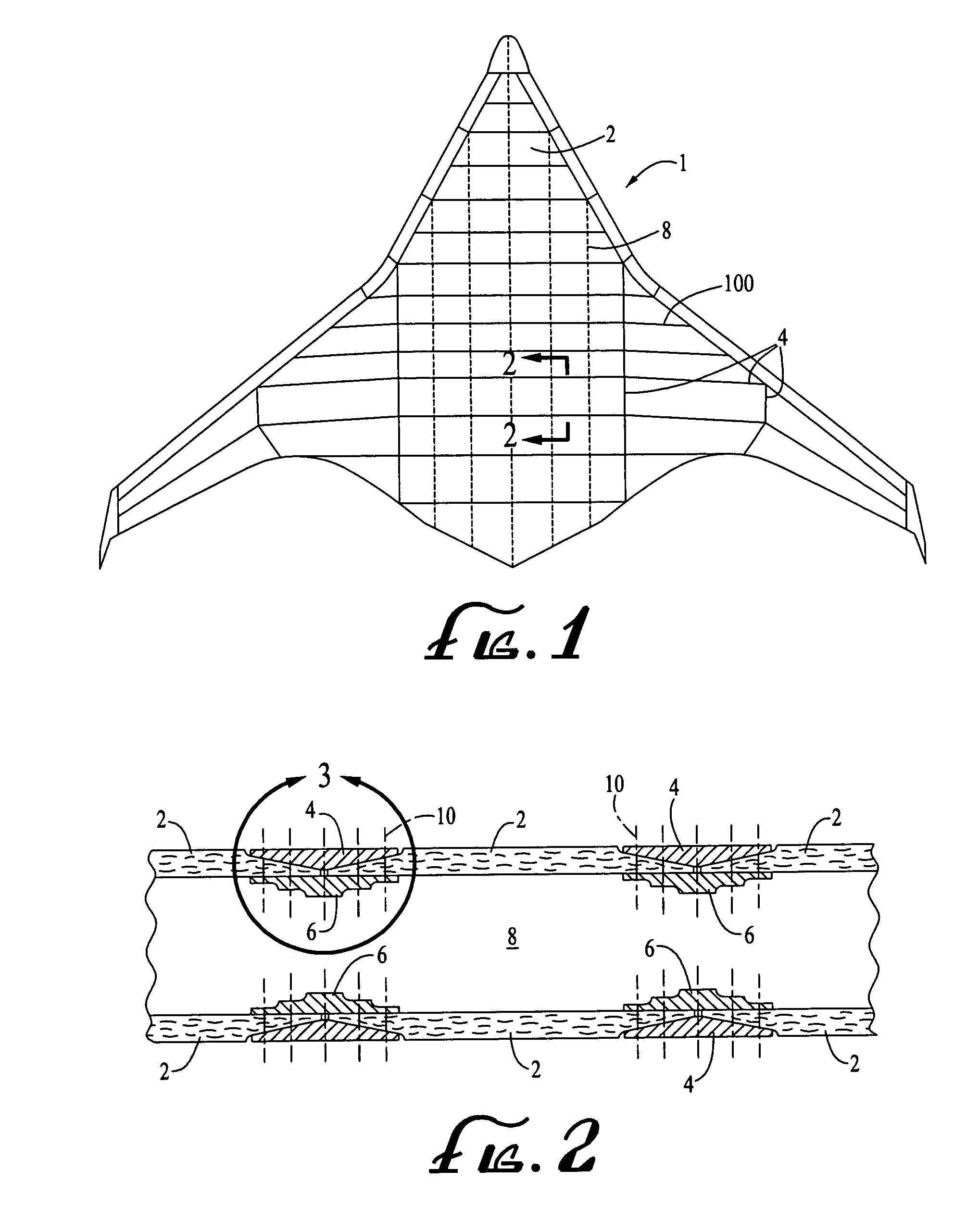
[0019]FIG. 1 is a top plan view of a composite, BWB-type of aircraft 1 incorporating one embodiment of the present lightning damage protection system 100. Although the system of the present embodiments is shown in conjunction with a BWB type of aircraft, it should be understood that the system is not limited to such aircraft types, but may be advantageously employed with conventional composite-bodied aircraft, as well.

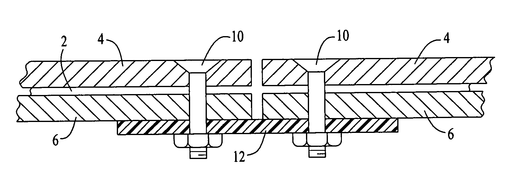
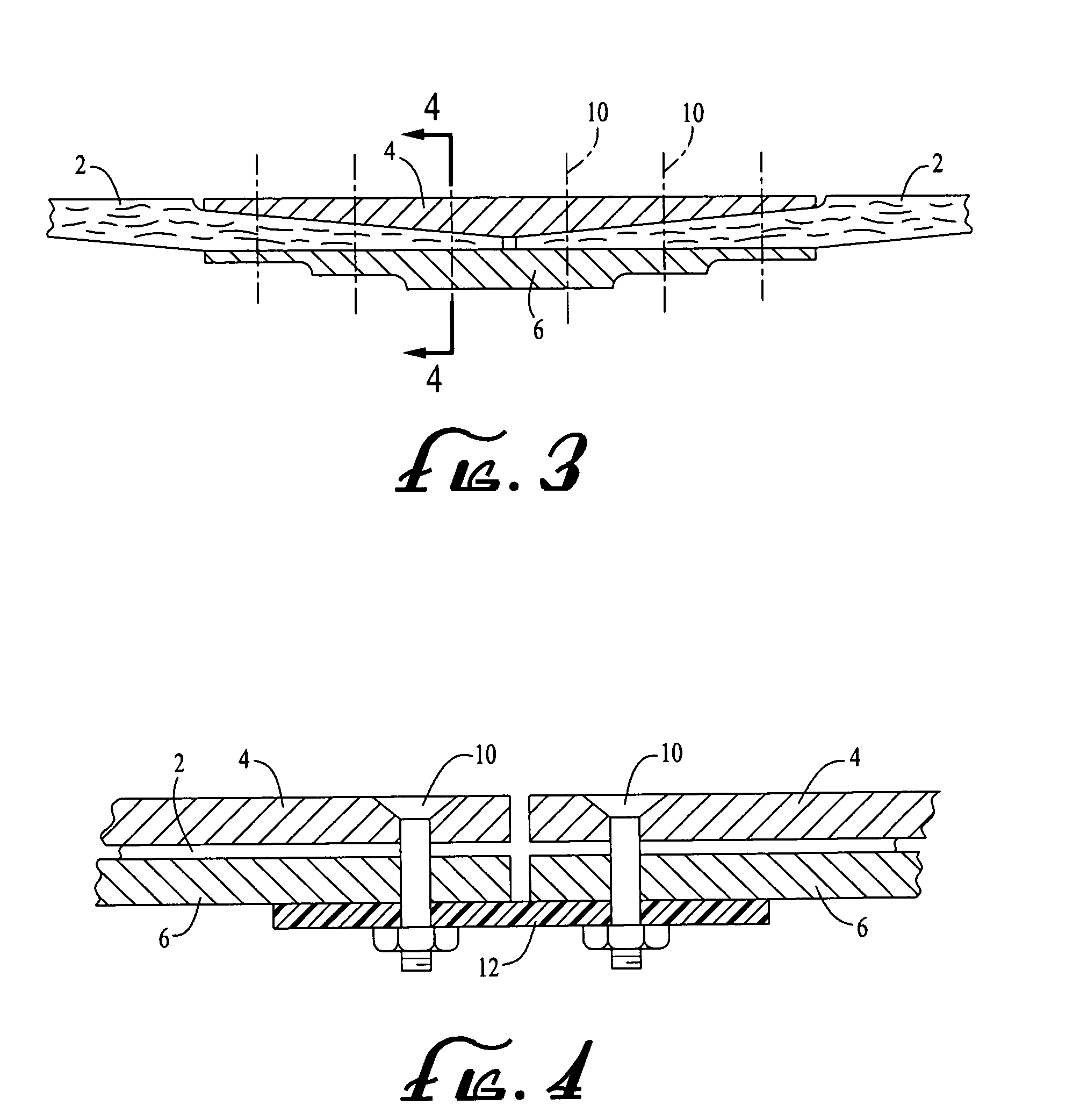
[0020]As illustrated in FIG. 1, the structure of the aircraft 1 may be seen to comprise a plurality of polygonal composite panels 2, i.e., structural skin panels made of plies of a fibrous material, e.g., “carbon” or graphite fibers, which are embedded in an epoxy resin to form a strong, rigid, light weight matrix. The panels are typically made, or “laid up,” separately, and then joined to each other at their respective edges by exterior and interior splice plates 4 and 6, respectively, as illustrated in the partial cross-sectional views of FIGS. 2 and 3. The aircraft ...


PUM


Abstract

A system for protecting a composite-body aircraft from damage caused by lightning strikes includes a Faraday cage defined on the exterior surface of the aircraft body by a continuous, electrically conductive grid that extends to the outermost lateral periphery of the body. In one possible embodiment in which the aircraft's body includes a plurality of composite panels that are joined at their adjacent edges by splice plates, the conductive grid may advantageously be formed by electrically conductive splice plates, e.g., of titanium, that have their respective, adjacent ends electrically connected to each other, e.g., with conductive straps and fasteners. The conductive grid provides preferential attachment points and conductive paths for lightning strikes on the surface of the aircraft, thereby shielding the interior of the grid from lightning damage. The conductive grid can optionally function as a ground return path for the aircraft's electrical system.

Description

BACKGROUND OF THE INVENTION[0001]1. Field of the Invention[0002]The present embodiments relate to lightning protection systems in general, and in particular, to a system for protecting composite-body aircraft from damage caused by lightning strikes.[0003]2. Related Art[0004]It is well accepted that composite (typically, carbon- or graphite-fiber-and-epoxy-resin matrices) structural components currently being incorporated into the bodies of advanced types of aircraft will be subjected to naturally occurring lightning discharges, or “strikes,” during flight. In a typical lightning strike incident, the lightning strikes, or “attaches,” at one extremity of an aircraft, and departs, or “detaches,” from another, resulting in a very large, momentary flow of electrical current through the body of the aircraft between the two points.[0005]The more severe, or “primary,” strikes tend to attach to and detach from the body of the aircraft at features that are located at or near protuberances at ...

Claims


Application Information

Patent Timeline
Patent Type & Authority Patents(United States)
IPC IPC(8): H05F3/00H02H1/00H02H1/04H02H3/22H02H7/20H02H9/06B64D45/02
CPCB64D45/02
Inventor HAWLEY, ARTHUR V
Owner THE BOEING CO
Learn More