Radar apparatus and optical receiver thereof

a technology of optical receiver and receiver body, which is applied in the field of radar, can solve the problems of raising the sensitive element, and increasing the physical size of the light receiving optical system (radar apparatus), so as to achieve the effect of enabling the detection of a wider angle range without increasing the volume of the receiver body and increasing reliability

Active Publication Date: 2009-07-07
DENSO CORP
View PDF3 Cites 12 Cited by
  • Summary
  • Abstract
  • Description
  • Claims
  • Application Information

AI Technical Summary

Benefits of technology

[0009]In view of the above and other problems, the present invention provides an optical receiver that is capable of detecting light in a wide angular range without increase in physical size and makes it possible to enhance the reliability of a light-sensitive element, and a radar device equipped with this optical receiver.
[0012]In this manner, an external light, e.g., a light reflected by a reflective object, is refracted by a refractive body having a greater refractive index than an external environment, e.g., air, with a refractile angle that is smaller than an incident angle. That is, the external light having an angle relative to an optical axis of the mirror has a smaller angle relative to the optical axis after refraction by the refractive body to be closely aligned with the optical axis. Therefore, a light receiving angle of the light receiving element after reflection by the mirror is widened (i.e., an incident angle range on an incidence angle of the refractive body is increased). Further, use of the mirror prevents the problem of the aberration of the condenser lens, thereby enabling detection of a wider angle range without increasing a volume of receiver body. Furthermore, an area of the light receiving element in the optical receiver can be made smaller than the one that does not have the refractive body when the external light is collected from the same range of the angle.
[0013]In addition, the optical receiver is not integrally composed with a light emission unit, thereby having an increased reliability.

Problems solved by technology

This results in an increased physical size of a light receiving optical system (radar apparatus).
However, the construction disclosed in Patent Document 2 involves another problem.
This increases the physical size of the light receiving optical system (radar apparatus).
Therefore, there is the possibility that the temperature of a light-sensitive element is raised, and the characteristics of the element are degraded (the reliability of the light-sensitive element is degraded).

Method used


Image

  • Radar apparatus and optical receiver thereof
  • Radar apparatus and optical receiver thereof
  • Radar apparatus and optical receiver thereof

Examples


first embodiment

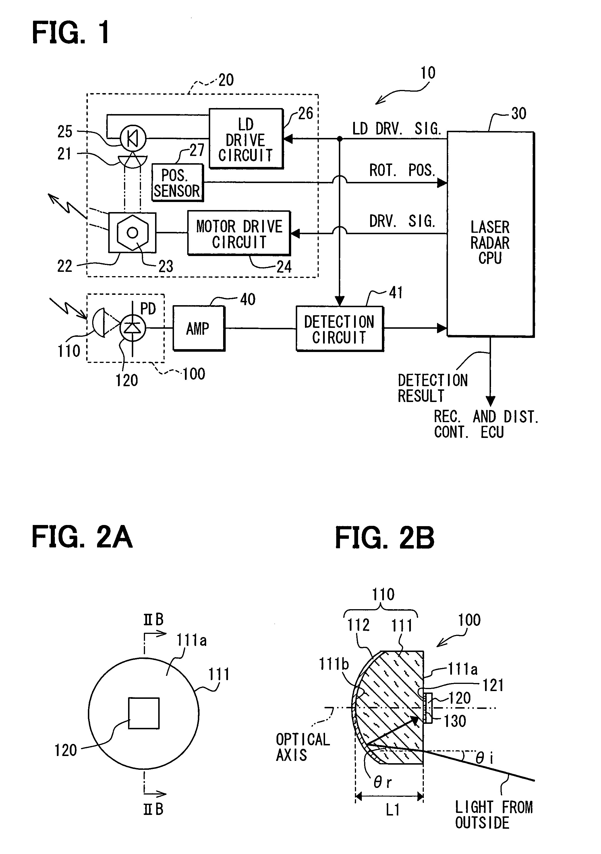
[0031]First, description will be given to the general configuration of a laser radar sensor to which an optical receiver in a first embodiment is applied. FIG. 1 is a general block diagram illustrating an example of the laser radar sensor. The invention is characterized in the configuration of the optical receiver. The radar device (not shown) including the laser radar sensor is described, for example, in JP-A-2005-257405, filed by the present applicants, and the like. Therefore, the detailed description of the radar device is omitted. The following description takes as an example a case where the radar device is used as a radar device for vehicles. However, the radar device according to the invention is not limited to those for vehicles, and can be used to detect any intruder into a specific area.

[0032]As illustrated in FIG. 1, the laser radar sensor 10 is constructed of the following as principal parts: a light sender 20 that projects laser light; an optical, receiver 100 that rec...

second embodiment

[0049]Description will be given to a second embodiment of the invention with reference to FIG. 7. FIG. 7 is a sectional view illustrating the general configuration of an optical receiver 100 in a second embodiment of the invention, and it corresponds to FIG. 2B referred to in relation to the first embodiment. In FIG. 7, the adhesive 130 is omitted.

[0050]As illustrated in FIG. 7, this embodiment is characterized in that the opposite face 111b of the refractive body 111 is constructed as a paraboloid and the concave mirror 112 is constructed as a parabolic mirror 112. More specific description will be given. The light-sensitive element 120 having the rectangular light receiving surface 121 is fixed in a position overlapping the optical axis on the incidence surface 111a between the parabolic mirror 112 and its focal point.

[0051]When this construction is adopted, the same phenomenon as with the spherical surface mirror described in relation to the first embodiment takes place. As illus...

third embodiment

[0058]Description will be given to a third embodiment of the invention with reference to FIG. 9. FIG. 9 is a sectional view illustrating the general configuration of an optical receiver 100 in the third embodiment of the invention, and it corresponds to FIG. 2B referred to in relation to the first embodiment. In FIG. 9, the adhesive 130 is omitted.

[0059]As illustrated in FIG. 9, this embodiment is characterized in that: the opposite face 111b of the refractive body 111 is constructed as an ellipsoid (eccentric ellipsoid in which the mirror surface intersects its minor axis in FIG. 9); and the concave mirror 112 is constructed as an ellipsoidal mirror 112. The light-sensitive element 120 having the rectangular light receiving surface 121 is fixed in a position overlapping the optical axis on the incidence surface 111a.

[0060]When this construction is adopted, the same phenomenon as with the spherical surface mirror described in relation to the first embodiment takes place. As illustr...


PUM


Abstract

A radar apparatus has a light receiver that includes a refractive body and a mirror on an opposite surface of the refractive body relative to an incidence surface of the refractive body for receiving an incident light from an outside of the radar apparatus. The refractive angle of the refractive body is configured to be smaller than an incident angle of the incident light, and the mirror is configured to reflect at least a portion of the incident light toward a first light receiving element that is disposed on the incidence surface with its light receiving face facing the incidence surface of the refractive body.

Description

CROSS REFERENCE TO RELATED APPLICATION[0001]This application is based on and claims the benefit of priority of Japanese Patent Application No. 2006-177106 filed on Jun. 27, 2006, the disclosure of which is incorporated herein by reference.FIELD OF THE INVENTION[0002]The present invention generally relates to a radar for use in a vehicle.BACKGROUND INFORMATION[0003]As radar devices, conventionally, there have been known those disclosed in Patent Documents 1 and 2, for example.[0004]A radar device disclosed in Patent Document 2 is so constructed that the following is implemented: light receiving unit (photodiode) is placed in an enclosure that constructs an illuminating lamp (headlight); reflected light reflected by a reflective object is reflected by a reflector that constructs the headlight; and it is further reflected by a second reflector and received by the receiving unit. More specifically, the reflected light reflected by the reflective object is received by the receiving unit ...

Claims


Application Information

Patent Timeline
Patent Type & Authority Patents(United States)
IPC IPC(8): G02B17/00G01C3/06G01J1/02G01J1/04G01S7/48G01S7/481G01S17/10G01S17/93
CPCG01S7/4811G01S7/4817G02B5/1814G02B27/4227G02B27/0037G02B27/4216G02B17/0856
Inventor KATOH, HISAYAMATSUSHITA, NORIYUKI
Owner DENSO CORP
Why Eureka
Try Eureka