Power output apparatus, motor vehicle equipped with power output apparatus, and control method of power output apparatus

a technology of power output and motor vehicle, which is applied in the direction of motor/generator/converter stopper, dynamo-electric converter control, gearing, etc., can solve the problems of raising the torque level to be cancelled by the motor, and worsening the drive feeling, so as to achieve the effect of enhancing the driving performan

Active Publication Date: 2009-07-14
TOYOTA JIDOSHA KK
View PDF12 Cites 12 Cited by
  • Summary
  • Abstract
  • Description
  • Claims
  • Application Information

AI Technical Summary

Benefits of technology

[0004]When the drive shaft is to be rotated in the reverse direction simultaneously with the power output from the internal combustion engine, the prior art power output apparatus may control the internal combustion engine and the generator to drive the internal combustion engine at an efficient drive point of the low rotation speed and the high torque. This control enhances the total energy efficiency of the power output apparatus, while increasing the torque for normal rotation transmitted from the internal combustion engine to the drive shaft. This undesirably raises the torque level to be cancelled by the motor and may prevent reverse rotation of the drive shaft with a sufficient torque. The prior art power output apparatus may otherwise control the internal combustion engine and the generator to drive the internal combustion engine at a drive point of the high rotation speed and the low torque. This control decreases the torque for normal direction transmitted from the internal combustion engine to the drive shaft and lowers the torque level to be cancelled by the motor, thus ensuring reverse rotation of the drive shaft with a sufficient torque. Setting the drive point of the internal combustion engine independently of the driver's operation worsens the drive feeling, since the internal combustion engine may be driven at a drive point different from the driver's expected drive point.
[0005]The power output apparatus, the motor vehicle equipped with the power output apparatus, and the control method of the power output apparatus of the invention aim to improve drive feeling in reverse rotation of a drive shaft while ensuring output of a required driving force. The power output apparatus, the motor vehicle equipped with the power output apparatus, and the control method of the power output apparatus of the invention also aim to enhance a driving performance in reverse rotation of the drive shaft.

Problems solved by technology

This undesirably raises the torque level to be cancelled by the motor and may prevent reverse rotation of the drive shaft with a sufficient torque.
Setting the drive point of the internal combustion engine independently of the driver's operation worsens the drive feeling, since the internal combustion engine may be driven at a drive point different from the driver's expected drive point.

Method used


Image

  • Power output apparatus, motor vehicle equipped with power output apparatus, and control method of power output apparatus
  • Power output apparatus, motor vehicle equipped with power output apparatus, and control method of power output apparatus
  • Power output apparatus, motor vehicle equipped with power output apparatus, and control method of power output apparatus

Examples


first embodiment

A. First Embodiment

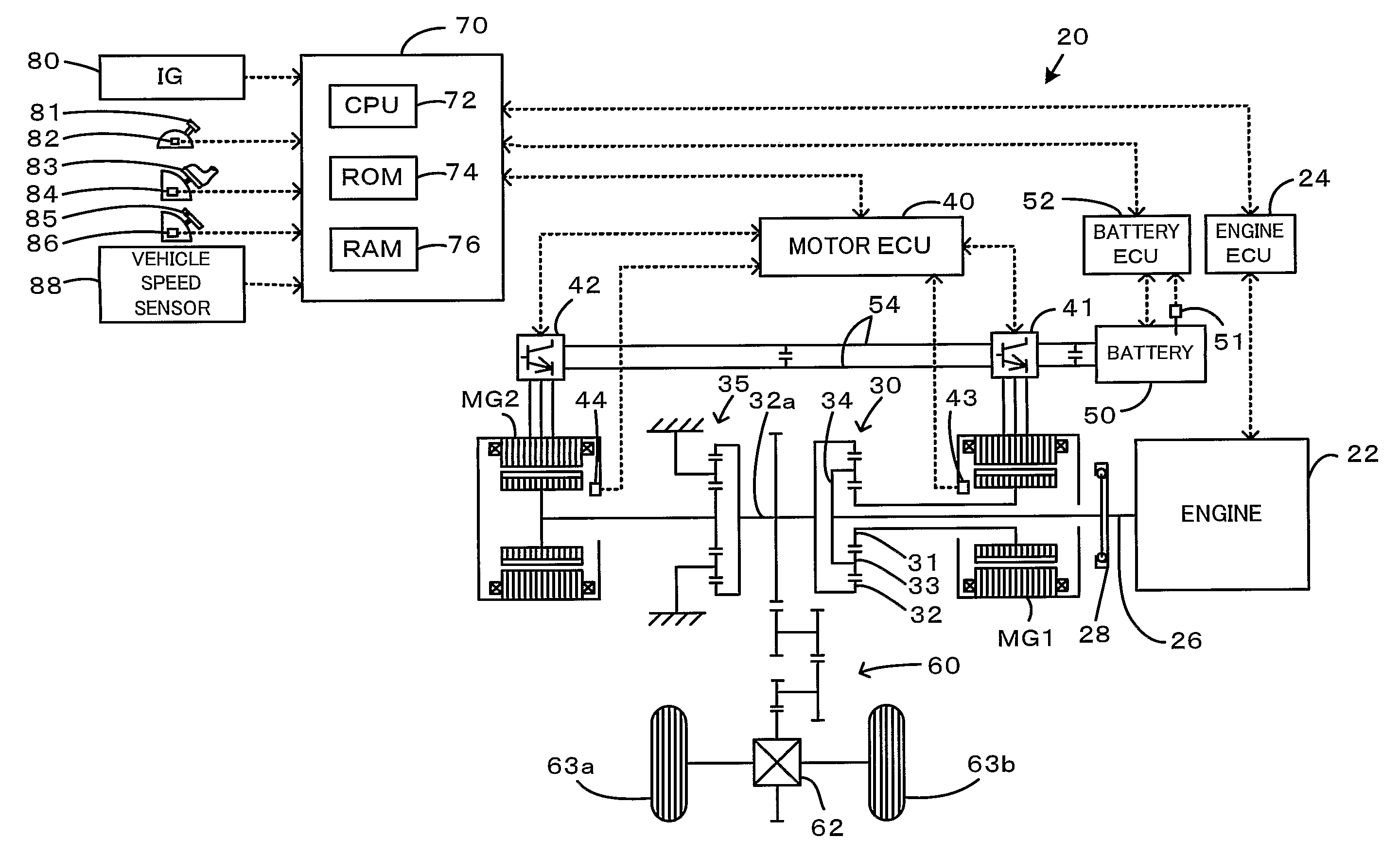
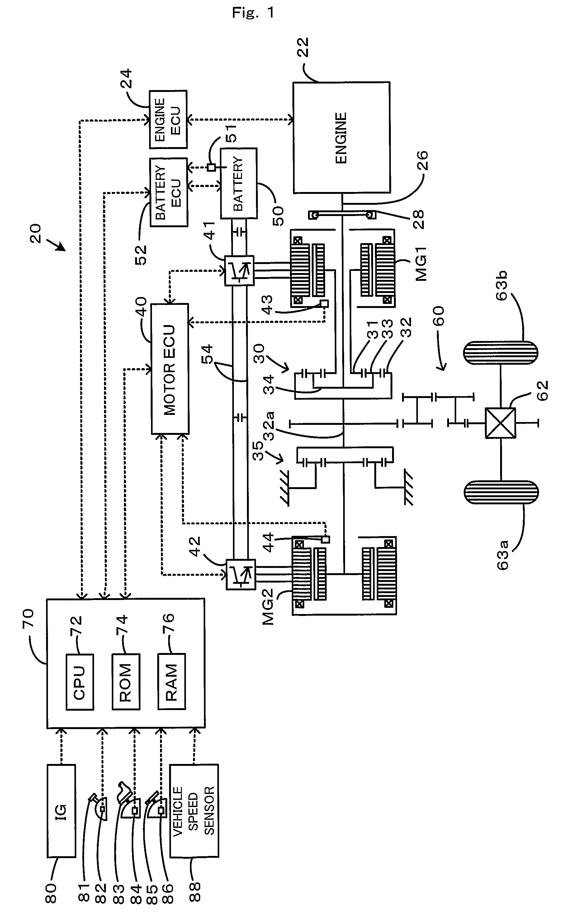
[0044]FIG. 1 schematically illustrates the construction of a hybrid vehicle 20 with a power output apparatus mounted thereon in one embodiment of the invention. As illustrated, the hybrid vehicle 20 of the first embodiment includes an engine 22, a three shaft-type power distribution integration mechanism 30 that is linked with a crankshaft 26 functioning as an output shaft of the engine 22 via a damper 28, a motor MG1 that is linked with the power distribution integration mechanism 30 and is capable of generating electric power, a reduction gear 35 that is attached to a ring gear shaft 32a functioning as a drive shaft connected with the power distribution integration mechanism 30, another motor MG2 that is linked with the reduction gear 35, and a hybrid electronic control unit 70 that controls the whole power output apparatus.

[0045]The engine 22 is an internal combustion engine that uses a hydrocarbon fuel, such as gasoline or light oil, to output power. An engine...

second embodiment

B. Second Embodiment

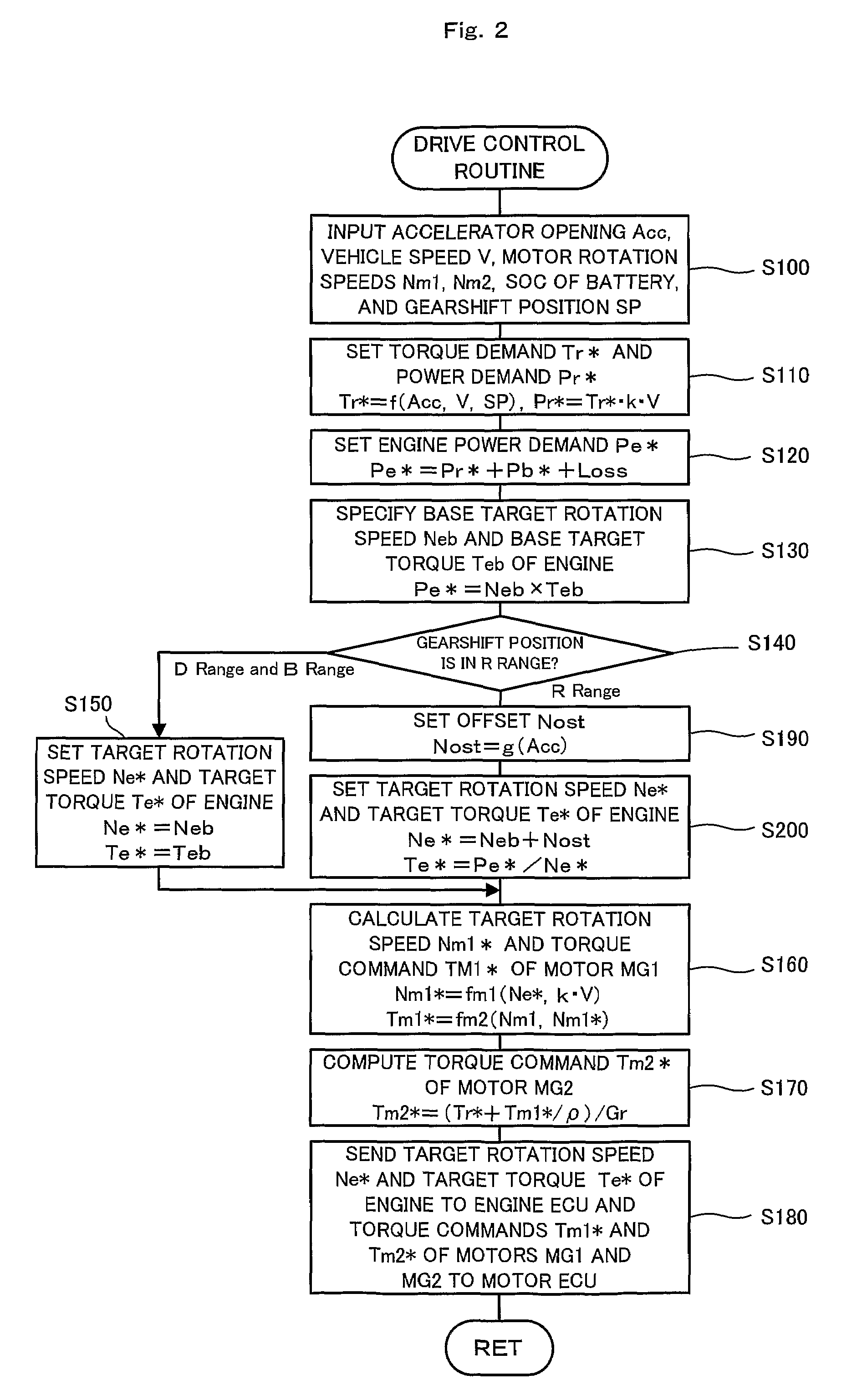
[0071]A hybrid vehicle 20B is described below as a second embodiment of the invention. The hybrid vehicle 20B of the second embodiment has the identical hardware configuration with that of the hybrid vehicle 20 of the first embodiment. The constituents and elements of the hybrid vehicle 20B of the second embodiment identical with those of the hybrid vehicle 20 of the first embodiment are thus expressed by the like numerals and symbols and are not specifically described here. FIG. 12 is a flowchart showing a drive control routine executed by the hybrid electronic control unit 70 included in the hybrid vehicle 20B of the second embodiment. This drive control routine is carried out repeatedly at preset time intervals (for example, at every 8 msec) during operation of the engine 22.

[0072]In the drive control routine of the second embodiment, the CPU 72 of the hybrid electronic control unit 70 first inputs various data required for control, that is, the accelerator op...


PUM


Abstract

In a reverse drive with power output from an engine, the control procedure of the invention selects a drive point of the higher rotation speed corresponding to the higher accelerator opening among available drive points that ensure output of a target engine power, and controls the engine to be driven at the selected drive point and ensure output of a torque demand corresponding to the accelerator opening to a drive shaft. A required torque level output from a motor MG2 increases with an increase in engine torque under the conditions of a fixed torque demand of the drive shaft and a fixed output power level of the engine 22. Setting a drive point of the higher rotation speed and the lower torque corresponding to a higher level of the accelerator opening ensures output of the torque demand to the drive shaft. Setting a drive point of the lower rotation speed and the higher torque corresponding to a lower level of the accelerator opening improves the drive feeling of the engine.

Description

[0001]This is a 371 national phase application of PCT / JP2005 / 013537 filed 19 Jul. 2005, claiming priority to Japanese Patent Applications No. 2004-211912 filed 20 Jul. 2004, and No. 2004-269937 filed 16 Sep. 2004, the contents of which are incorporated herein by reference.TECHNICAL FIELD[0002]The preset invention relates to a power output apparatus, a motor vehicle equipped with the power output apparatus, and a control method of the power output apparatus. More specifically the invention pertains to a power output apparatus that outputs power to a drive shaft, and a motor vehicle that is equipped with such a power output apparatus and is driven via an axle linked to the drive shaft, as well as to a control method of such a power output apparatus.BACKGROUND ART[0003]One proposed power output apparatus has a generator, an internal combustion engine, and a drive shaft that are respectively connected to a sun gear, a carrier, and a ring gear of a planetary gear mechanism, and a motor t...

Claims


Application Information

Patent Timeline
Patent Type & Authority Patents(United States)
IPC IPC(8): F16H3/72B60K1/02F16H37/06H02P1/00H02P3/00H02P7/00B60L50/15B60K6/20B60K6/445B60K6/448B60K6/52B60L50/16B60W10/04B60W10/06B60W10/08B60W10/10B60W10/101B60W10/26B60W20/00F02D29/02
CPCB60K6/445B60L11/12B60W10/06B60W10/08B60W30/18036B60K6/365B60K1/02Y10T477/30B60W20/00B60W2710/0644Y02T10/6286Y02T10/7005Y02T10/7077Y02T10/6239Y10S903/93Y10T477/23B60L50/15Y02T10/62Y02T10/7072Y02T10/70
Inventor AMANO, MASAYAKAITA, KEIJI
Owner TOYOTA JIDOSHA KK
Why Eureka
Try Eureka