Display module

a technology of display module and display module, which is applied in the direction of identification means, electrical apparatus casings/cabinets/drawers, instruments, etc., can solve the problems of increasing the manufacturing cost of display module, generating a large amount of heat, and not being able to effectively dissipate the heat generated by the ic chip, etc., to achieve rapid transfer of heat generated, easy manufacturing, and dissipation of heat

Inactive Publication Date: 2009-07-14
SAMSUNG SDI CO LTD
View PDF28 Cites 13 Cited by
  • Summary
  • Abstract
  • Description
  • Claims
  • Application Information

AI Technical Summary

Benefits of technology

[0010]It is also an object of the present invention to provide for a practical heatsink for display modules that is easy to manufacture.
[0011]It is further an object of the present invention to provide a display module that uses a heatpipe capable of rapidly transferring heat generated at an IC chip to a chassis for dissipation of the heat to ambient air and thus has an improved heatsink effect.
[0012]It is yet an object of the present invention to provide a display module that uses a simple and inexpensive heatpipe capable improved heat dissipation and capable of keeping circuit drivers at a lower operation temperature without the need for a heatsink plate and / or a heatsink fan.

Problems solved by technology

In the plasma display device, the IC chip mounted on the signal transmitting unit generates a large amount of heat during the operation of the plasma display module.
However, such heatsinking arrangements do not make it possible to effectively dissipate the heat generated by the IC chip.
These arrangements, however, greatly increase the manufacturing costs of the display module.
Moreover, since a region where the signal transmitting units (such as the TCP) are disposed is very small, it is difficult to install a plurality of heatsink plates or fans.
Therefore, it is difficult to significantly improve the heatsink effect of the IC chip.

Method used


Image

  • Display module
  • Display module
  • Display module

Examples


Embodiment Construction

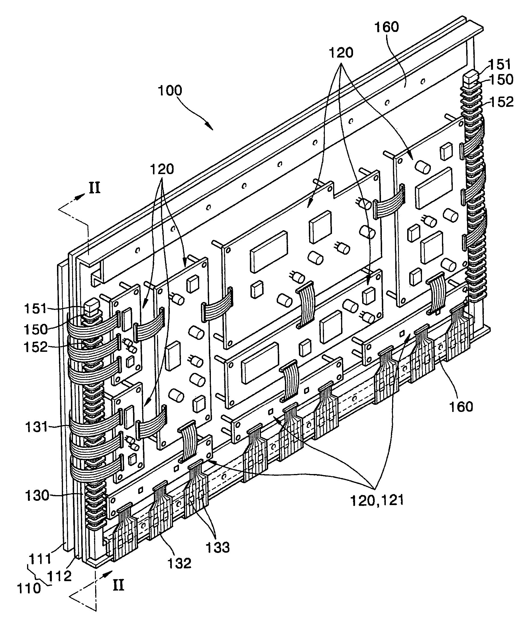
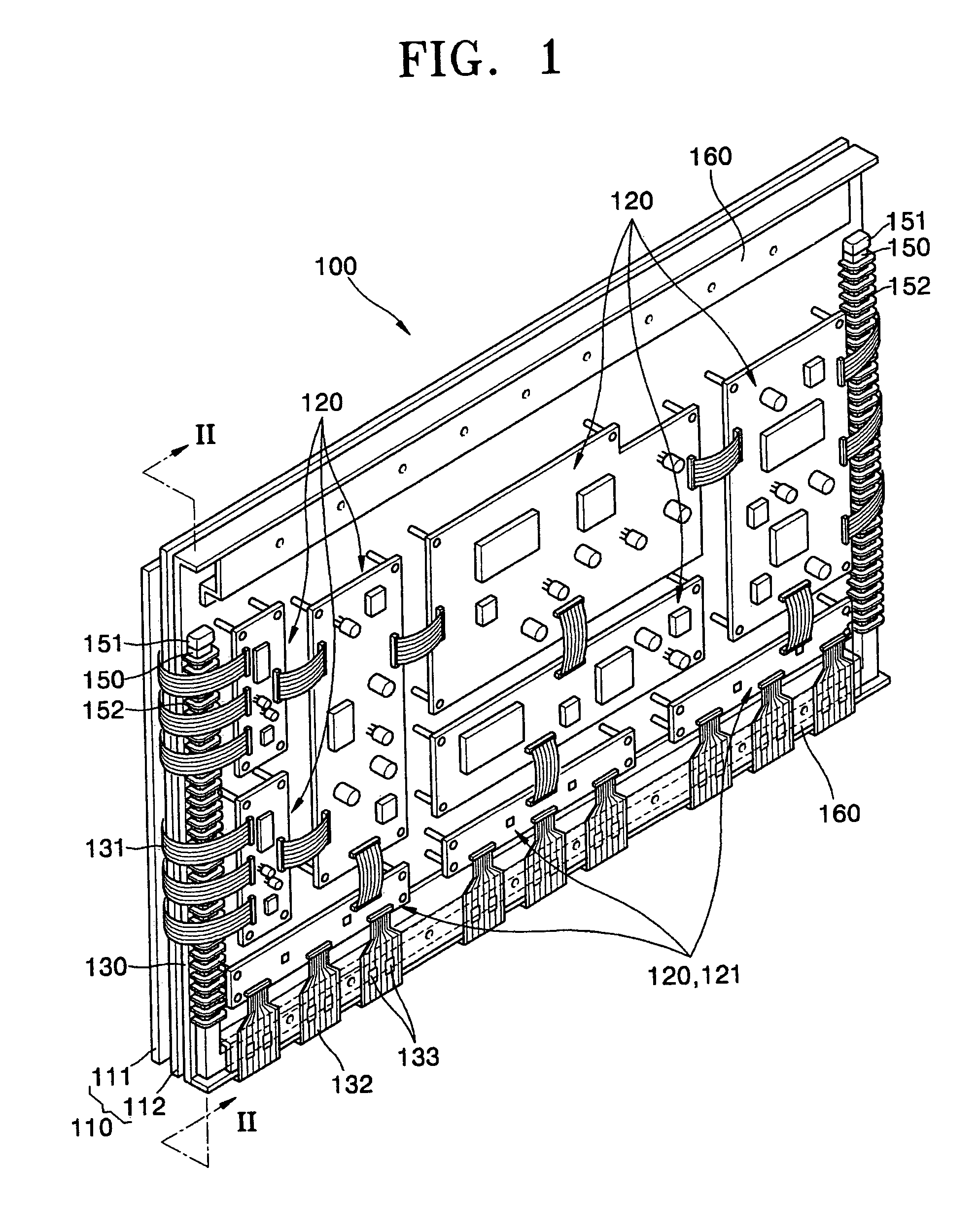
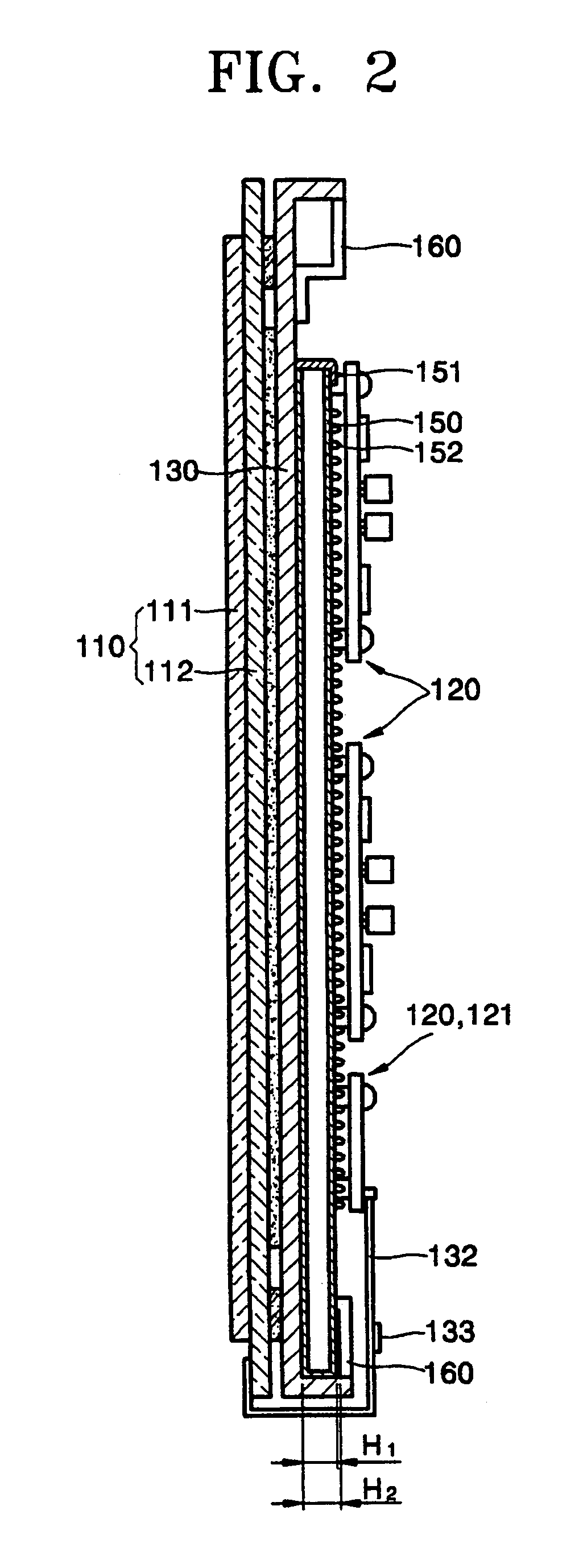
[0022]Turning now to the figures, FIG. 1 is a perspective view of a display module 100 according to an embodiment of the present invention, FIG. 2 is a sectional view taken along line II-II in FIG. 1 and FIG. 3 is a plan view of the chassis 130 of FIG. 1 with heatpipe 150 arranged thereon. Referring to FIGS. 1 through 3, the display module 100 includes a PDP 110 for producing an image. The PDP 110 can be any one of various types of PDPs. For example, the PDP 110 can be a 3-electrode AC surface-discharge PDP.

[0023]The PDP 110 includes a first panel 111 and a second panel 112 facing each other. Although not illustrated in FIG. 1, the first panel 111 includes a plurality of sustain electrode pairs disposed on a first substrate, a first dielectric layer covering the sustain electrode pairs, and a protective layer coated on the first dielectric layer. The sustain electrode pairs include stripe-shaped common electrodes and scan electrodes. Although not shown, the second panel 112 includes...


PUM


Abstract

Provided is a display module having an improved heatsink. The display module includes a display panel adapted to display an image, a chassis adapted to support the display panel, a driver circuit unit arranged on the chassis and adapted to generate an electrical signal that drives the display panel, an integrated circuit arranged on a signal transmitting unit, the integrated circuit being adapted to control signal transmission between the driver circuit unit and the display panel and at least one heatpipe arranged on a side of the chassis opposite the display panel, the heatpipe being adapted to transfer heat generated by the IC chip to the chassis.

Description

CLAIM OF PRIORITY[0001]This application makes reference to, incorporates the same herein, and claims all benefits accruing under 35 U.S.C. § 119 from an application for PLASMA DISPLAY MODULE earlier filed in the Korean Intellectual Property Office on 12 Apr. 2005 and there duly assigned Serial No. 10-2005-0030366.BACKGROUND OF THE INVENTION[0002]1. Field of the Invention[0003]The present invention relates to a display module, and more particularly, to a display module having an improved heatsink.[0004]2. Description of the Related Art[0005]The plasma display device is a widely used display device because of its small thickness and high-quality wide screen with a having viewing angle. A display module is a key component of a display device, and includes a display panel, a driving circuit unit for driving the display panel, and a chassis for supporting the driving circuit unit and the display panel. A display module used in the plasma display device includes a plasma display panel (PD...

Claims


Application Information

Patent Timeline
Patent Type & Authority Patents(United States)
IPC IPC(8): H05K7/20G09F9/00
CPCH05K7/2099F28D15/0266F28D15/0275H01J17/28H01J11/34
Inventor JEONG, KWANG-JIN
Owner SAMSUNG SDI CO LTD
Why Eureka
Try Eureka