Solver for simulating a system in real time on a programmable hardware element

a hardware element and solver technology, applied in the field of real-time simulation, can solve the problems of dangerous or economically infeasible, inability to perform or monitor a test, inability to simulate a real system, and inability to achieve real-time simulation, etc., and achieve the effect of quick and easy chang

Active Publication Date: 2009-07-21
NATIONAL INSTRUMENTS
View PDF13 Cites 13 Cited by
  • Summary
  • Abstract
  • Description
  • Claims
  • Application Information

AI Technical Summary

Benefits of technology

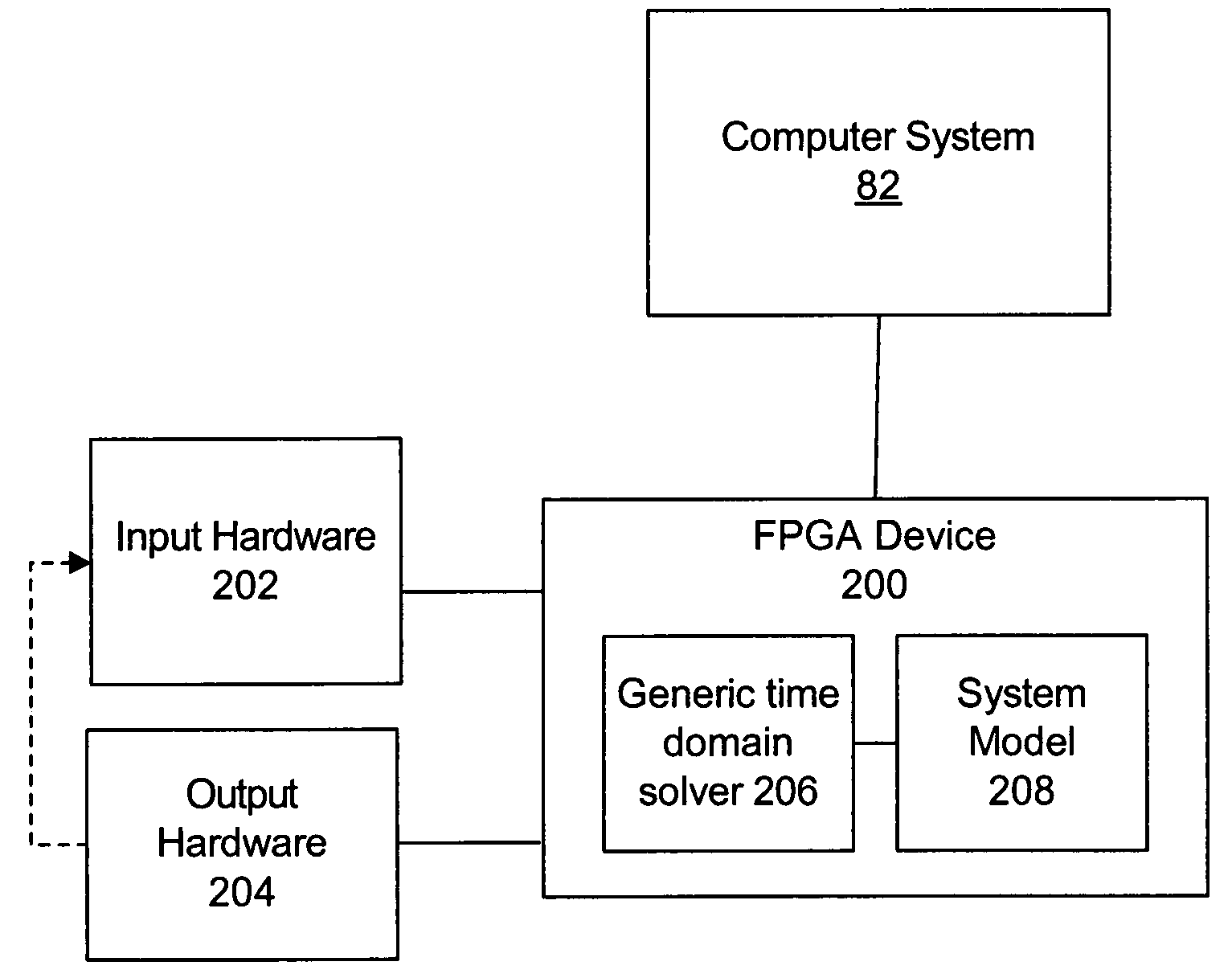
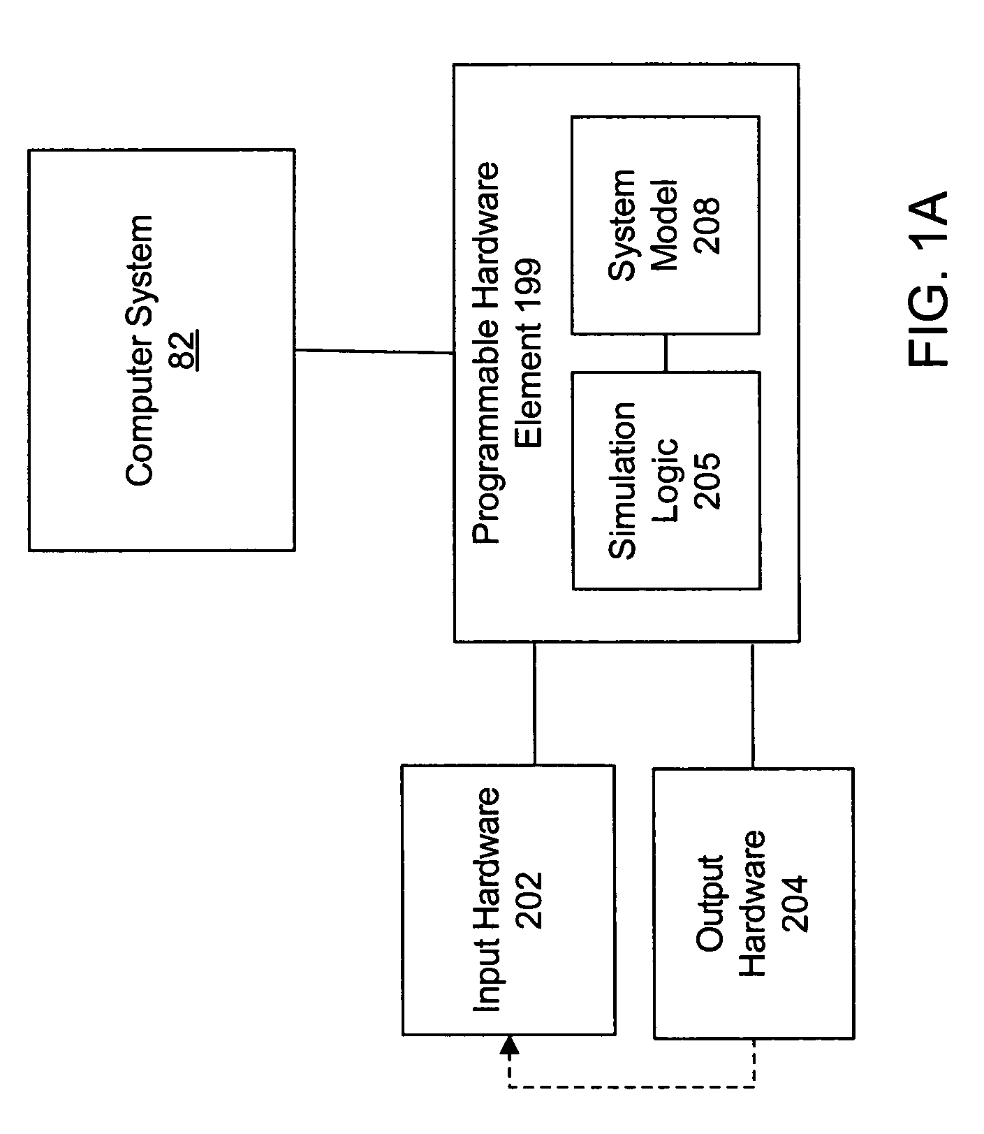
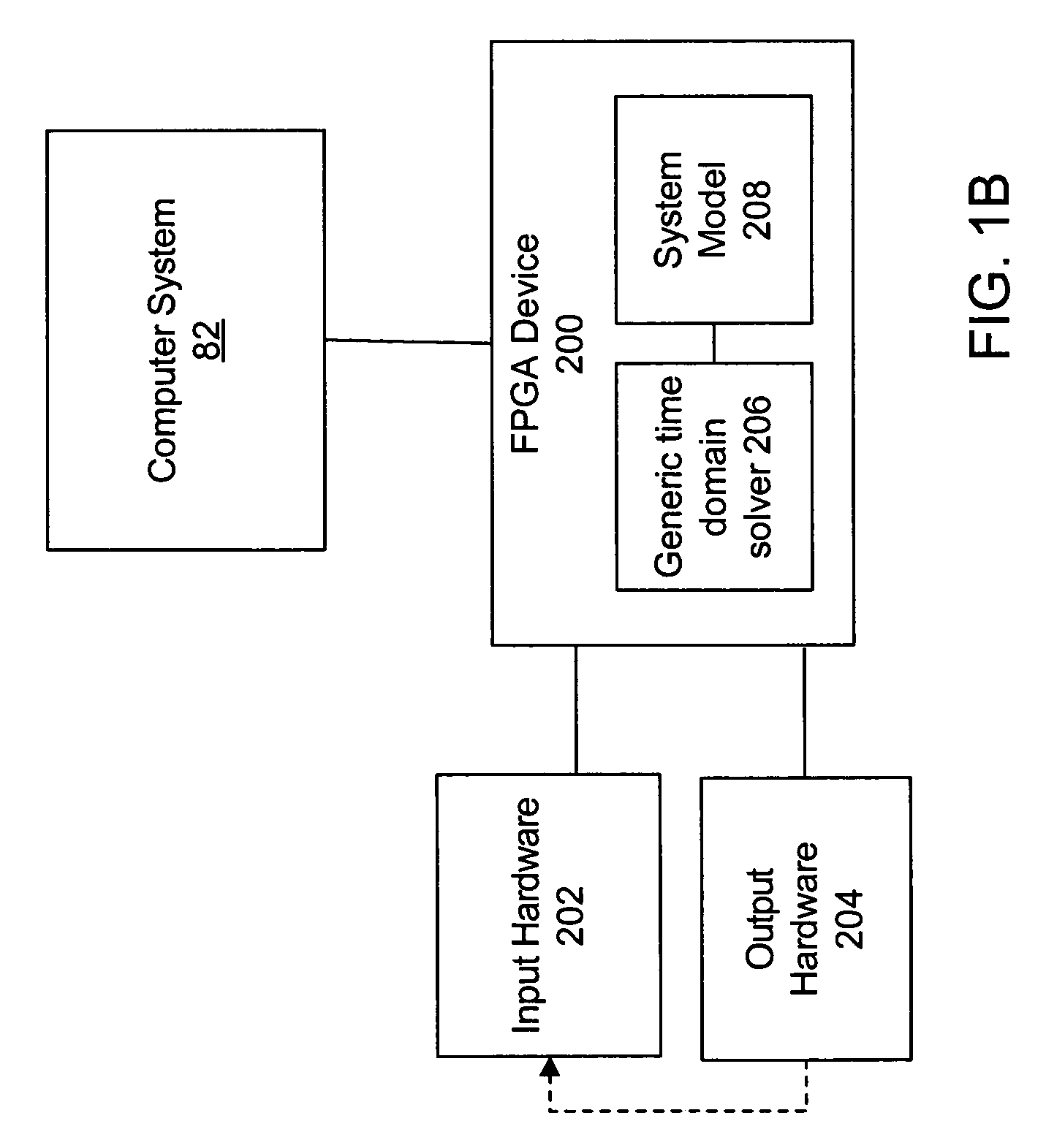
[0013]One embodiment of the present invention comprises a system and method for performing a simulation of a system, optionally in real time. The system includes a programmable hardware element, such as a Field Programmable Gate Array (FPGA) device, Programmable Logic Device (PLD), or other device that includes reconfigurable or programmable hardware. The programmable hardware element may be configured with simulation logic (a solver), thus allowing a very fast execution of the simulation.
[0015]The system may be reconfigured to simulate different systems simply by changing the system model, e.g., by updating the registers on the FPGA with different matrix coefficients representing a different model. In other words, the simulation logic may comprise “generic” logic for simulating different systems, depending on the particular system model with which the programmable hardware element is configured. The simulation logic may be modularized from the system model so that the programmable hardware element can quickly be reconfigured to simulate a different system model without requiring the programmable hardware element to be reconfigured with different simulation logic. Thus the system described herein may provide for fast execution, using an FPGA-implemented solver, while also being quickly reconfigurable with different system models.
[0017]The generic time domain solver is referred to herein as “generic” because it is operable to perform a time domain simulation of different systems by simply reconfiguring the FPGA device with a different system model. The generic time domain solver may be modularized from the system model so that the FPGA device can easily and quickly be reconfigured with a different system model, without requiring the generic time domain solver to be changed. The logic or solver may comprise an FPGA implementation, e.g., a net list or bit file which is implemented on an FPGA, which requires a large amount of time to replace. In contrast, the system model comprise a plurality of model matrix coefficients that are stored in random access memory (RAM), such as a computer's RAM, and which may be loaded into registers in the FPGA. Thus the solver, which is expensive (in terms of time) to modify or replace, is generic and is preferably stored once on the FPGA, and provides a very fast execution. Thereafter different system models (comprising matrix coefficients stored in RAM) may be loaded into registers of the FPGA in a matter of microseconds. Thus the FPGA-based solver can be easily reconfigured with different system models very quickly and efficiently.
[0021]The system described above may enable simulations of many types of systems to be performed, optionally in real time. By configuring the FPGA device or other programmable hardware element to implement the simulation, the simulation may proceed much faster than if the simulation were performed in software executing on a computer system. Also, the simulation of the system may be performed using real-world input hardware and output hardware. In other words, the simulation may be performed using the same input / output hardware that would be used together with an actual physical implementation of the system being modeled, where little or no modification is required to the input / output hardware. Moreover, the system model may be quickly and easily changed, which can enable users to ascertain and understand the effects of various modifications to the system under simulation.

Problems solved by technology

As another example, in many situations, it may be necessary to test the measurement / control logic that will be used in an actual measurement / control loop, but it may be infeasible, impractical, or impossible to do so with the real system.
For example, it may be necessary to test whether the measurement / control logic will work properly under extreme or emergency situations in which it would be dangerous or economically infeasible to perform the test with a real system, e.g., due to the possibility of harm to the system or the environment of the system.
Also, the real system may operate under conditions that make it impossible to perform or monitor a test, as in a space flight or deep-sea dive.
When traditional text-based programming environments are used, the user's programming skills and ability to interact with the computer system often become a limiting factor in the achievement of optimal utilization of the computer system.
There are numerous subtle complexities which a user must master before he can efficiently program a computer system in a text-based environment.
The task of programming a computer system to model or implement a process often is further complicated by the fact that a sequence of mathematical formulas, steps or other procedures customarily used to conceptually model a process often does not closely correspond to the traditional text-based programming techniques used to program a computer system to model such a process.
Since a user often is not fully proficient in techniques for programming a computer system in a text-based environment to implement his solution, the efficiency with which the computer system can be utilized often is reduced.

Method used


Image

  • Solver for simulating a system in real time on a programmable hardware element
  • Solver for simulating a system in real time on a programmable hardware element
  • Solver for simulating a system in real time on a programmable hardware element

Examples


Embodiment Construction

Incorporation by Reference

[0048]The following references are hereby incorporated by reference in their entirety as though fully and completely set forth herein:

[0049]U.S. Pat. No. 5,481,741: titled “Method and Apparatus for Providing Attribute Nodes in a Graphical Data Flow Environment”.

[0050]U.S. Pat. No. 6,173,438: titled “Embedded Graphical Programming System” filed Aug. 18, 1997.

[0051]U.S. Pat. No. 6,219,628: titled “System and Method for Configuring an Instrument to Perform Measurement Functions Utilizing Conversion of Graphical Programs into Hardware Implementations,” filed Aug. 18, 1997.

[0052]U.S. Patent Application Publication No. 20010020291: (Ser. No. 09 / 745,023) titled “System and Method for Programmatically Generating a Graphical Program in Response to Program Information,” filed Dec. 20, 2000.

[0053]U.S. patent application Ser. No. 10 / 046,861: titled, “System and Method for Performing a Hardware in the Loop Simulation Using a Plurality of Graphical Programs that Share a ...


PUM


Abstract

A method for performing a simulation of a system. The system includes an FPGA that is configured to implement simulation logic, such as a generic solver. For example, the FPGA device may implement a generic time domain solver or a generic frequency domain solver. The FPGA device is also configured with information representing a system model of the system under simulation. The system also includes input hardware for providing input signals for the simulation to the FPGA device and output hardware for receiving output signals computed by the simulation from the FPGA device. The system may be reconfigured to simulate different systems by changing the system model, without requiring the simulation logic (e.g., the generic solver) to be changed.

Description

FIELD OF THE INVENTION[0001]The present invention relates to the field of real-time simulation. More particularly, the invention relates to a solver implemented in hardware, where the solver is operable to perform real time simulations for different systems without requiring changes to the solver itself.DESCRIPTION OF THE RELATED ARTSystem Simulation[0002]Simulation of a system may be implemented using software, hardware, or a combination of both. Creating a system simulation typically involves creating a model of the system, where the model represents the system or represents certain aspects of the system. For a given system, the system may be modeled in any number of different ways. Thus, the type of model that is created may depend on the particular aspects of the system that the modeler is interested in or the particular purpose of performing the simulation. For example, depending on the particular system and the particular problem to be solved, modeling the system may involve c...

Claims


Application Information

Patent Timeline
Patent Type & Authority Patents(United States)
IPC IPC(8): G06F9/45H03K17/693
CPCG06F17/5027G06F30/331
Inventor MORIAT, ALAIN
Owner NATIONAL INSTRUMENTS
Why Eureka
Try Eureka