High efficiency, inductive vibration energy harvester

a high-efficiency, inductive vibration technology, applied in the direction of dynamo-electric machines, dynamo-electric components, magnetic bodies, etc., can solve the problems of loss of charge, device limitation, change of charge charge on the capacitor, etc., to enhance the magnetic flux emerging from the magnet end, high magnetic permeability material, and high permeability

Inactive Publication Date: 2009-08-04
FERRO SOLUTIONS
View PDF26 Cites 131 Cited by
  • Summary
  • Abstract
  • Description
  • Claims
  • Application Information

AI Technical Summary

Benefits of technology

[0018]In accordance with the principles of the invention, an inductive energy harvester comprises a permanent magnet magnetic field source attached by a pair of compact spiral disk springs to an induction coil. The springs position the magnet so that the induction coil surrounds one end of the magnet where the change in flux density is highest. In addition, the magnetic flux emerging from that end of the magnet is enhanced and directed toward the coil by a disk of high magnetic permeability material, such as soft iron. The coil and magnet are also surrounded by a return flux yoke made of a magnetic material having high permeability and high flux density. The flux yoke further enhances the magnetic flux changes through the coil by reducing magnetic field fringing effects (the yoke provides a low-reluctance return path for the flux).

Problems solved by technology

Thus, a vibration causes a change in charge on the capacitor when a voltage is applied to the device.
However, because this device is limited in its charge, the load resistance must be high to prevent rapid loss of charge.
Consequently, the power produced by inductive energy harvesters is presently limited by coil size (NA), the magnitude of the vibration amplitudes and frequencies (to increase
However, in a practical system, as the load impedance decreases, current flows and, in accordance with Lenz's law, generates a back EMF that opposes the motion of the magnet and opposes the induced voltage thereby reducing the power output.

Method used


Image

  • High efficiency, inductive vibration energy harvester
  • High efficiency, inductive vibration energy harvester
  • High efficiency, inductive vibration energy harvester

Examples


Embodiment Construction

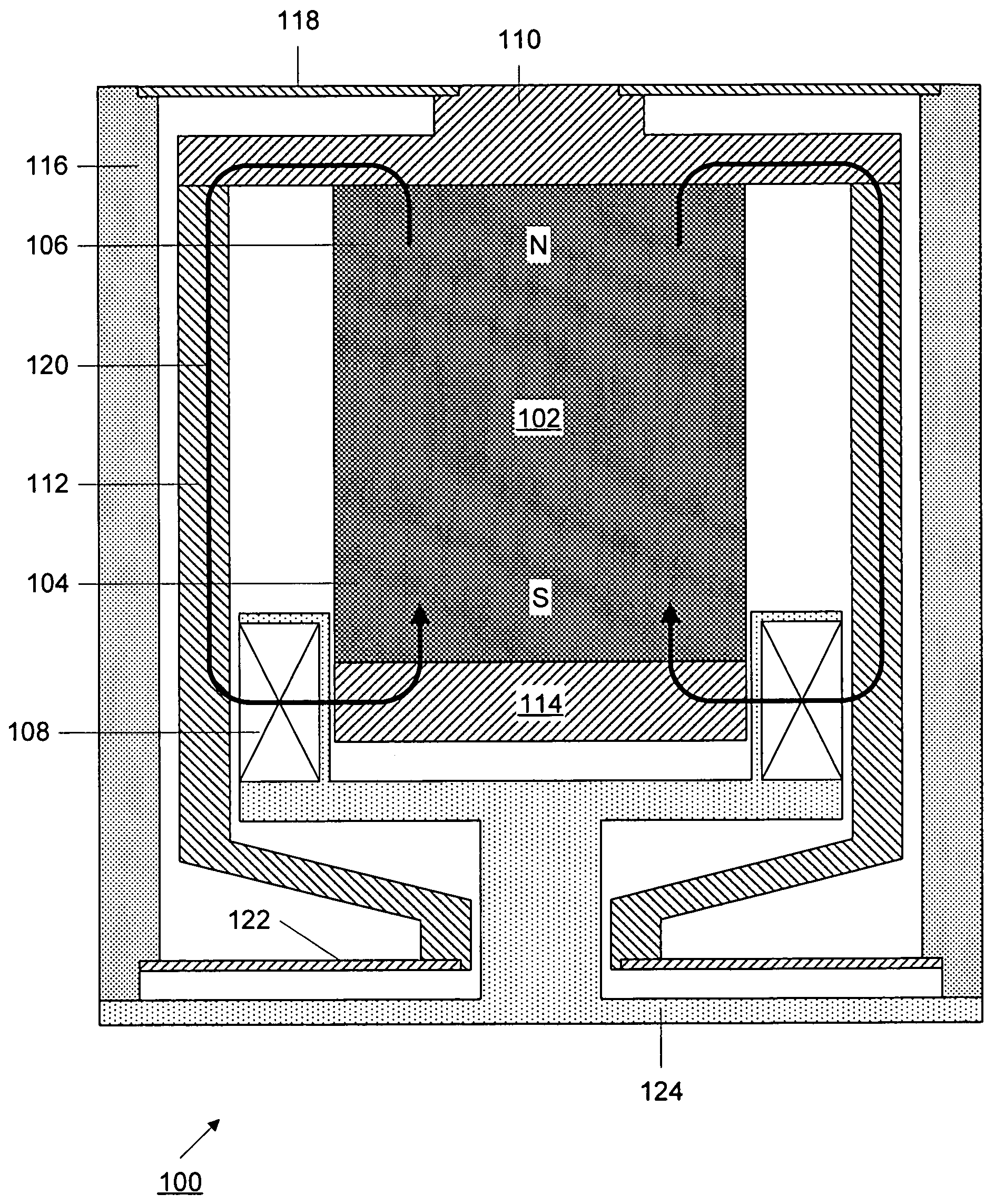
[0030]It is generally believed that once the mechanical resonance part of an energy harvester has been optimized, it makes little difference which mode of transduction (capacitive, electroactive or magnetic induction is used. (see, for example, “Analysis of a micro electric generator for Microsystems”, C. B. Williams and R. B. Yates, Sensors and Actuators, A52, pp. 8-11, (1996) and “A study of low level vibrations as a power source for wireless sensor nodes”, S. Roundy, P. K. Wright and J. M. Rabaey, Computer Communications, v. 26, n. 11, pp. 1131-1144 (2003)). We have found this not to be the case. We have made several inductive vibration energy harvesters of comparable volumes and improvements in design have led to more than an order of magnitude increase in power output, now at about 9 mW for vibrations at 21 Hz having an acceleration of 0.1 g (1 ms−2).

[0031]FIG. 1 shows a schematic partial cross-sectional diagram of an inductive energy harvester 100 constructed in accordance wit...


PUM


Abstract

An inductive energy harvester comprises a permanent magnet magnetic field source attached by a pair of compact spiral disk springs to an induction coil. The springs position the magnet so that the induction coil surrounds one end of the magnet where the flux density is greatest. In addition, the magnetic flux emerging from that end of the magnet is enhanced by a disk of magnetic material having high permeability and high flux density. In another embodiment, the magnetic field source comprises two dipole magnets arranged in opposing flux relationship with a thin layer of high flux density, high magnetic permeability material located in a gap between the magnets.

Description

RELATED APPLICATIONS[0001]This application claims the benefit of U.S. provisional application 60 / 463,537, filed Apr. 18, 2003.FIELD OF THE INVENTION[0002]This invention relates to apparatus and methods for converting small mechanical movements, such as vibrations and oscillations, into electrical energy.BACKGROUND OF THE INVENTION[0003]An energy harvester is a device that converts mechanical movements into electrical energy. This electrical energy can then be stored or used by other devices. Thus, an energy harvester of this type can utilize energy that would otherwise be lost. For example, the vibrations of an air duct can be converted to electrical energy by an energy harvester and the electrical energy can be then be used to power a sensor that measures the temperature of air in that duct. Therefore, the sensor will not require periodic battery changes.[0004]Applications of such energy harvesters include supplementing other power sources or recharging batteries, thereby extending...

Claims


Application Information

Patent Timeline
Patent Type & Authority Patents(United States)
IPC IPC(8): H02K33/00
CPCH02K35/02H01F7/1615
Inventor BONO, DAVID C.SLISKI, ALANHUANG, JIANKANGO'HANDLEY, ROBERT C.
Owner FERRO SOLUTIONS
Why Eureka
Try Eureka