
Method for removing mercury in exhaust gas and system therefor

a technology of exhaust gas and mercury, applied in the direction of emission prevention, separation process, lighting and heating apparatus, etc., to achieve the effect of reducing cost, increasing the removal rate of mercury in exhaust gas, and absorbing and removing more surely

Active Publication Date: 2009-08-11
MITSUBISHI POWER LTD
View PDF6 Cites 9 Cited by
  • Summary
  • Abstract
  • Description
  • Claims
  • Application Information

AI Technical Summary

Benefits of technology

[0007]As a result, the inventors found that the above-described problem can be solved by controlling the oxidation-reduction potential (ORP) in the absorbing solution by the forced blowing of air into a scrubber or the addition of an oxidizing agent and hence prevent mercury chloride from being reduced into vapor mercury. The present invention was completed from this point of view.
[0009]In the present invention, the mercury removing method can further include an effluent treatment process in which products in the absorbing solution are oxidized by an acid or an oxidizing agent. Furthermore, the mercury removing method can further include a gas-liquid contact process in which a cleaning solution, with which at least one of either air or an oxidizing agent is mixed, is brought into contact with exhaust gas having been subjected to the contact process, and a second contact process in which the oxidation-reduction potential of the cleaning solution is controlled.
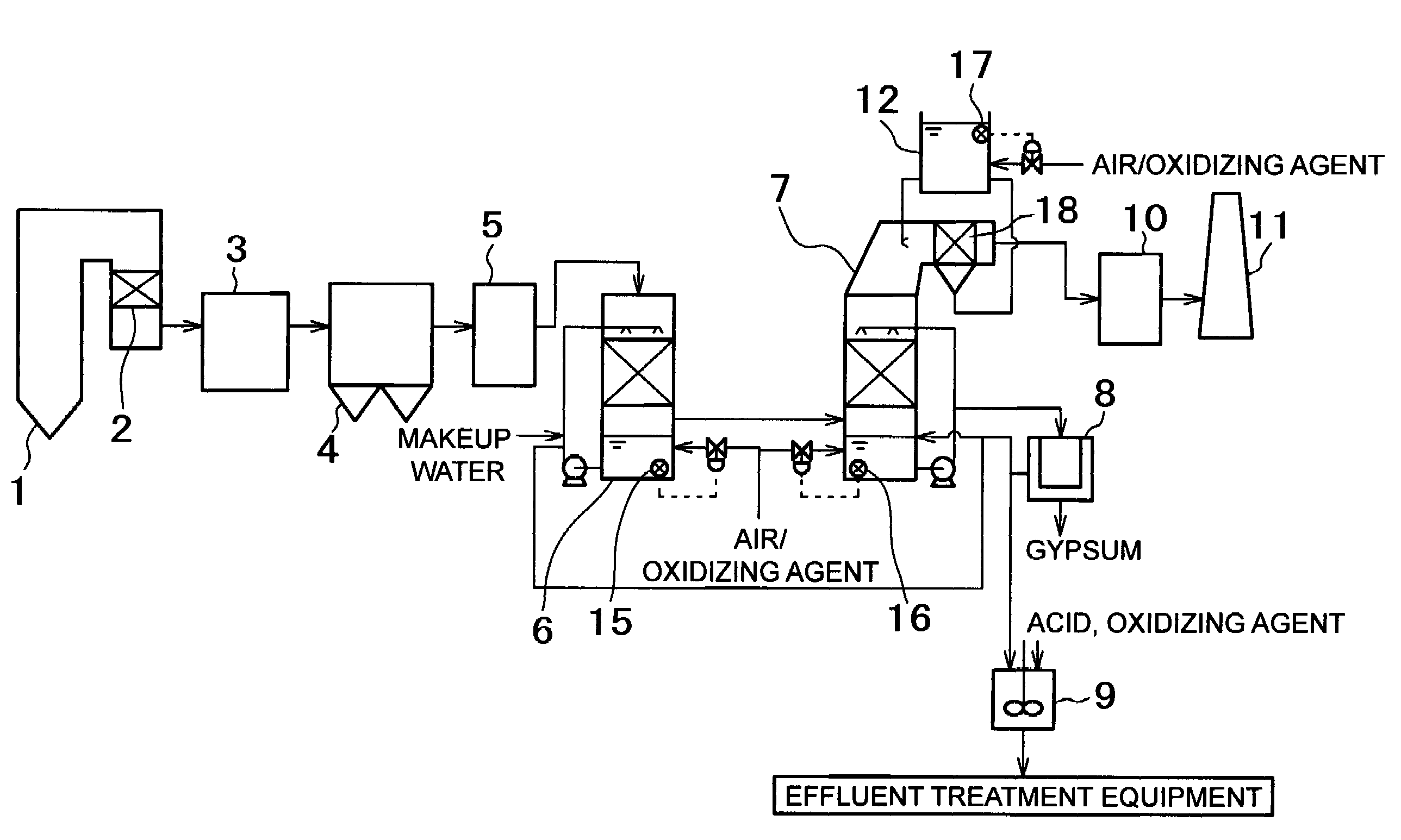
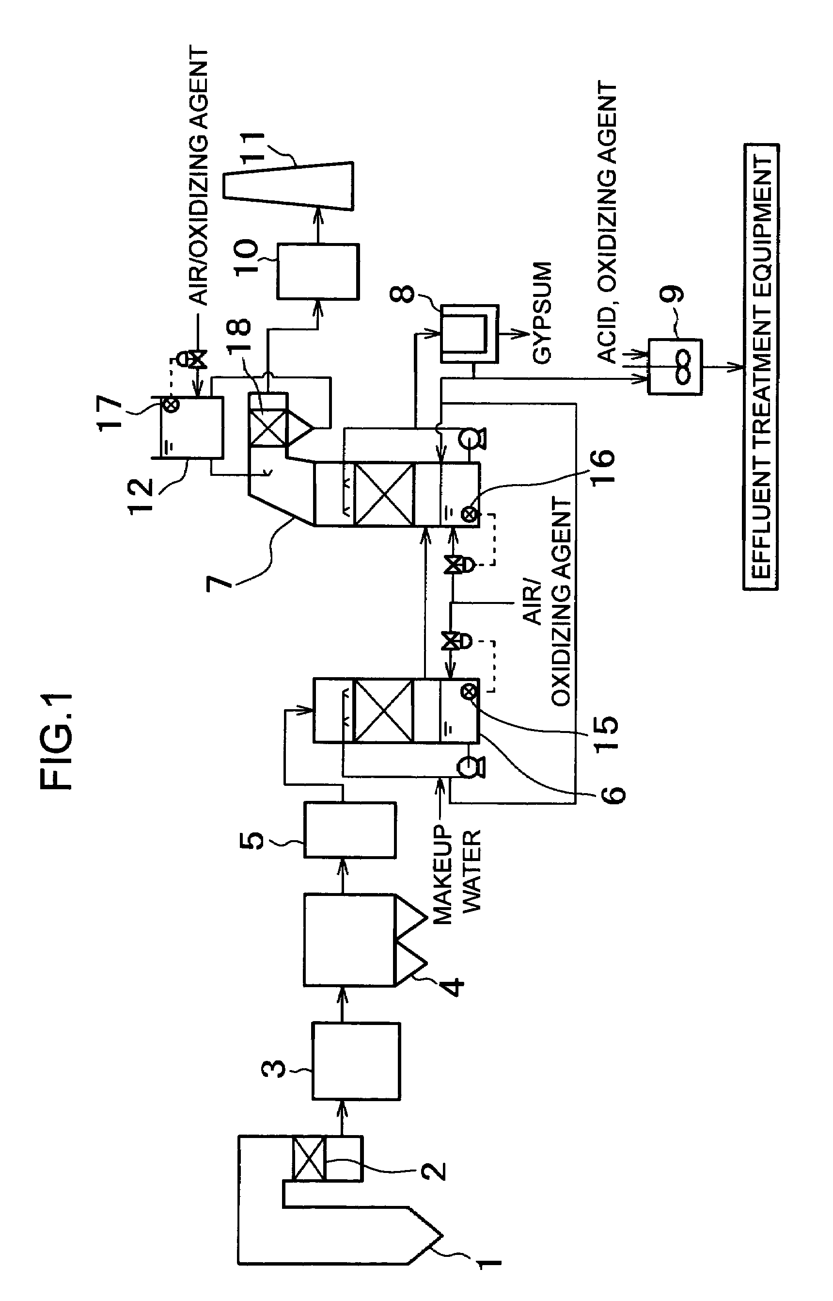
[0012]In another mode of the present invention, the mercury conversion process, in which metallic mercury in exhaust gas is converted to mercury chloride, is carried out in the presence of the mercury oxidation catalyst provided between the denitrification catalyst provided on the downstream of the combustion equipment and the scrubber. In the case where an air heater (air preheater), a dust collector, a heat exchanger, and the like are provided in the system, the mercury oxidation catalyst can be provided on the upstream or downstream side of these apparatuses. However, it is preferable that the mercury oxidation catalyst be provided in a temperature zone of, for example, 60 to 200° C. where a reaction into mercury chloride takes place easily even when the concentration of HCl in exhaust gas is low. In this case, metallic mercury can be converted to mercury chloride by using HCl contained in exhaust gas.
[0015]In addition, in the present invention, the gas-liquid contact section (for example, mist eliminator (M / E) cleaning spray section etc.) for bringing the cleaning solution to which air or an oxidizing agent is added in contact with exhaust gas can be provided at the outlet of the scrubber such as the desulfurization absorption tower. At this time, it is preferable that the cleaning solution be sprayed into exhaust gas after the ORP in a cleaning solution tank is controlled by the blowing of air or the addition of an oxidizing agent so as to be 600 mV or higher, which provides a region in which HgCl2 is stable, to prevent mercury having been removed once by the scrubber as HgCl2 from being reduced by SO2 and thereby being re-vaporized (Hg(g)).
[0016]According to the present invention, mercury can be absorbed and removed more surely by fixing mercury in the absorbing solution, so that the removal rate of mercury in exhaust gas can be increased. Also, mercury can be removed surely merely by providing ancillary equipment to the existing equipment, and an apparatus specially designed for mercury removal is not needed, so that space saving and a lower cost exhaust gas treatment system can be anticipated. Especially when air is used for oxidation, an oxidizing agent is not consumed, so that a low cost can be achieved easily.

Problems solved by technology

However, both of the above-described methods have a problem in that when the mercury having been oxidized once is trapped by a downstream scrubber such as a cooling tower and the desulfurization apparatus, it is reduced by the action of SO2 coexisting in flue gas, and is volatized again.

Method used


Image

  • Method for removing mercury in exhaust gas and system therefor
  • Method for removing mercury in exhaust gas and system therefor
  • Method for removing mercury in exhaust gas and system therefor

Examples


example 1

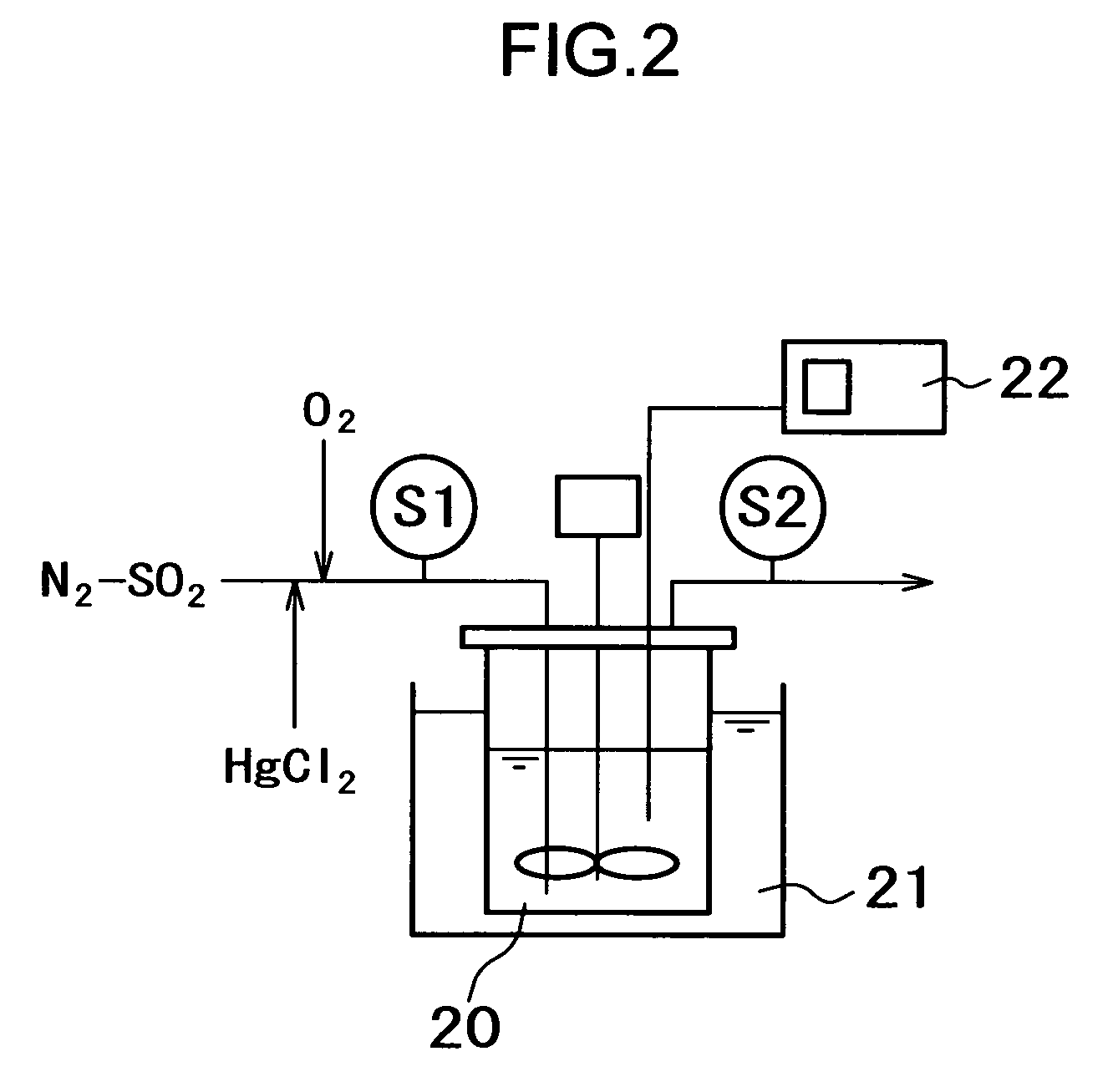
[0067]A test was carried out by using a mercury absorbing test device shown in FIG. 2 to examine a condition in which mercury chloride is reduced by sulfur oxide (SO2).

[0068]In the device of example 1, O2 was added to N2 gas containing SO2, and mercury chloride (HgCl2) was mixed thereto, by which a simulation gas was prepared. The simulation gas was introduced into a reactor 20 whose temperature was controlled by a constant-temperature bath 21, and was stirred by a stirring blade provided in the reactor 20. For the solution in the reactor 20, the oxidation-reduction potential thereof was measured by an ORP meter 22. The gas in the reactor 20 was discharged from an outlet on top of the reactor 20. An inlet gas was sampled at S1, and an outlet gas at S2.

[0069]The test conditions were as described below: the contents of added components were O2: 4.0%, 10%, SO2: 1000 ppm, and HgCl2: 10 μg / m3N, the pressure was ordinary pressure, the reactor temperature was 60° C., the solution compositi...

example 2

[0072]A test for evaluating the mercury removal rate was carried out by using a system for removing mercury in exhaust gas shown in FIG. 3.

[0073]In the system of example 2, combustion equipment for burning pulverized coal together with air, an air heater (A / H) 3, an electric dust collector 4, a mercury oxidation catalyst 13 kept warm by an electric heater 14, a cooling tower 6, a desulfurization absorption tower 7, a heat exchanger (GGH) 10, and a stack 11 are arranged in that order. The cooling tower 6 is provided with an introduction pipe for blowing air, and the introduction pipe is provided with a valve for regulating the amount of blown air. An opening / closing mechanism of the valve is connected to an electrometer 15 for measuring the oxidation-reduction potential of an absorbing solution in the cooling tower 6. Similarly, the desulfurization absorption tower 7 is also provided with an introduction pipe provided with a valve, and an opening / closing mechanism of the valve is con...

example 3

[0079]A test for evaluating the mercury removal rate was carried out by using a system for removing mercury in exhaust gas shown in FIG. 4.

[0080]In the system of example 3, combustion equipment for burning pulverized coal together with air, an air heater (A / H) 3, an electric dust collector 4, a mercury oxidation catalyst 13 kept warm by an electric heater 14, a desulfurization absorption tower 7, a heat exchanger (GGH) 10, and a stack 11 are arranged in that order. At the lower part of the desulfurization absorption tower 7 is provided an introduction pipe for blowing air, and the introduction pipe is provided with a valve for regulating the amount of blown air. An opening / closing mechanism of the valve is connected to an electrometer 16 for measuring the oxidation-reduction potential of an absorbing solution.

[0081]In an exhaust gas flow path on the downstream of the desulfurization absorption tower 7, a gas-liquid contact section 18 is provided. In the gas-liquid contact section 18...


PUM

PropertyMeasurementUnit
Electric potential / voltageaaaaaaaaaa
Concentrationaaaaaaaaaa

Abstract

The present invention provides a method for removing mercury in exhaust gas, in which mercury in exhaust gas discharged from combustion equipment is removed, characterized by including a mercury oxidation process in which mercury in the exhaust gas is converted to mercury chloride in the presence of a catalyst; a contact process in which the exhaust gas is brought into contact with an absorbing solution in a scrubber to absorb and remove mercury components from the exhaust gas; and a control process in which blowing of air or addition of an oxidizing agent into the scrubber is accomplished, and the amount of blown air or the added amount of oxidizing agent is regulated to control the oxidation-reduction potential of the absorbing agent, and a system for removing mercury in exhaust gas. According to the mercury removing method in accordance with the present invention, a phenomenon that mercury chloride is reduced into metallic mercury by SO2 etc. and the metallic mercury scatters in the exhaust gas can be prevented, and mercury in the exhaust gas can be decreased effectively.

Description

TECHNICAL FIELD[0001]The present invention relates to a mercury removing method for removing mercury in exhaust gas discharged from combustion equipment such as a boiler and a mercury removing system therefor.BACKGROUND ART[0002]In exhaust gas discharged from combustion equipment such as a coal or heavy oil fired boiler, hazardous trace substances such as mercury exist, so that it is necessary to remove these hazardous substances from exhaust gas. It is thought that the mercury in exhaust gas generally is present as water-insoluble metallic mercury (Hg) and water-soluble mercury chloride (HgCl2). Although mercury chloride, which is easily absorbed by water, can be removed by a desulfurization absorption tower or the like, metallic mercury, which has a very low solubility in water, is not absorbed by a desulfurization absorption tower, and may be discharged as metallic mercury vapor without being absorbed.[0003]Conventionally, therefore, there has been proposed, in addition to an act...

Claims


Application Information

Patent Timeline
IPC IPC(8): B01D53/64B01D53/50B01D53/86F23J15/00
CPCB01D53/501B01D53/8665F23J15/006F23J2219/40F23J2215/60B01D2257/602
Inventor HONJO, SHINTAROTAKASHINA, TORUIIDA, KOZOOKINO, SUSUMUTAKEUCHI, YASUHIRO
Owner MITSUBISHI POWER LTD
Learn More