
Method and apparatus for multiple scan rate swept wavelength laser-based optical sensor interrogation system with optical path length measurement capability

a technology of optical path length and interrogation system, which is applied in the direction of optical radiation measurement, counting objects on conveyors, instruments, etc., can solve the problem of delay in the return of optical signals to the detection circuitry, and achieve accurate measurement of sensor wavelength and accurate measurement of physical distance from the interrogation system

Active Publication Date: 2009-08-11
LUNA INNOVATIONS
View PDF25 Cites 10 Cited by
  • Summary
  • Abstract
  • Description
  • Claims
  • Application Information

AI Technical Summary

Benefits of technology

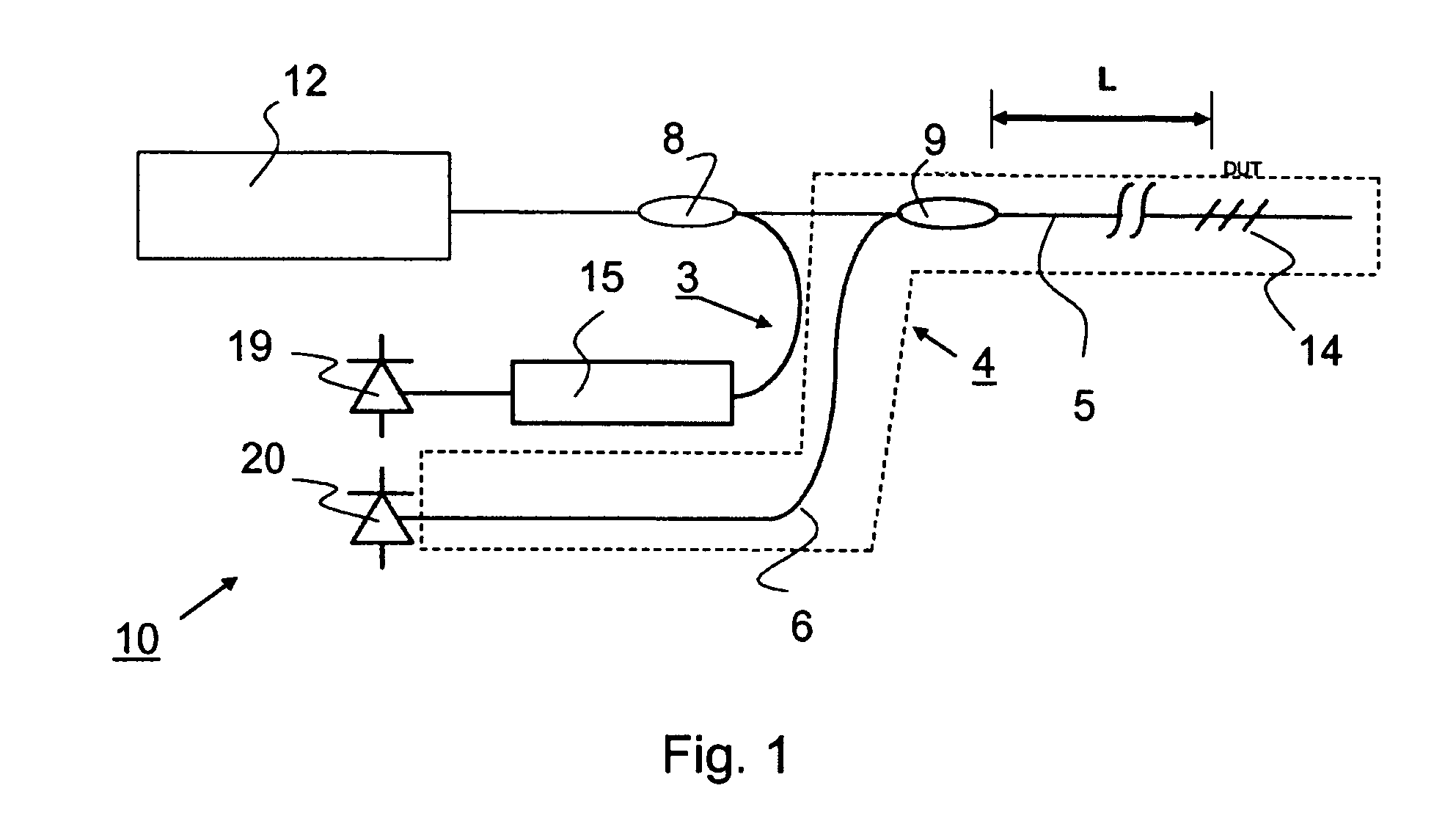
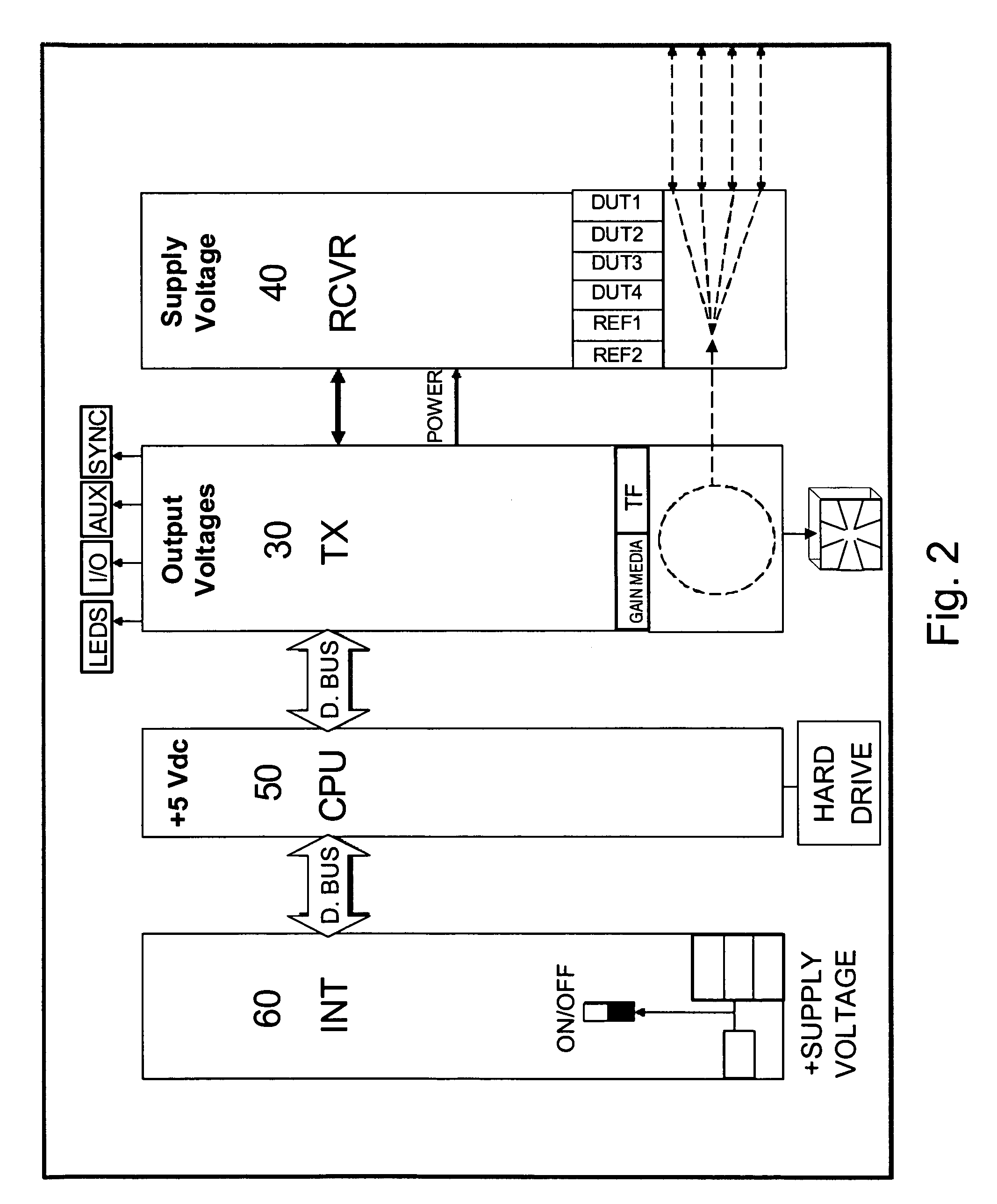
The invention is about a device and method to accurately measure the wavelength of optical sensors, such as fiber Bragg grating sensors, using a swept wavelength laser interrogator system. The device includes a swept wavelength optical source and an integrated optical wavelength reference. The apparatus and methods compensate for potential sensor wavelength error caused by the use of a swept wavelength laser source with a fixed wavelength reference. The device can measure the distance between the interrogator and the sensors with high accuracy. The invention is useful in sensor systems that generate multiple narrow band optical signals. The method uses multiple laser scan rates to determine the optical path length to the sensors and calculates the actual distance from the interrogator to the sensors. The invention provides a way to compensate for time-of-flight induced sensor measurement offsets and provides a more accurate measure of sensor wavelength. The device is automated and can perform the sensor optical path length measurements and calculate the appropriate wavelength correction factors.

Problems solved by technology

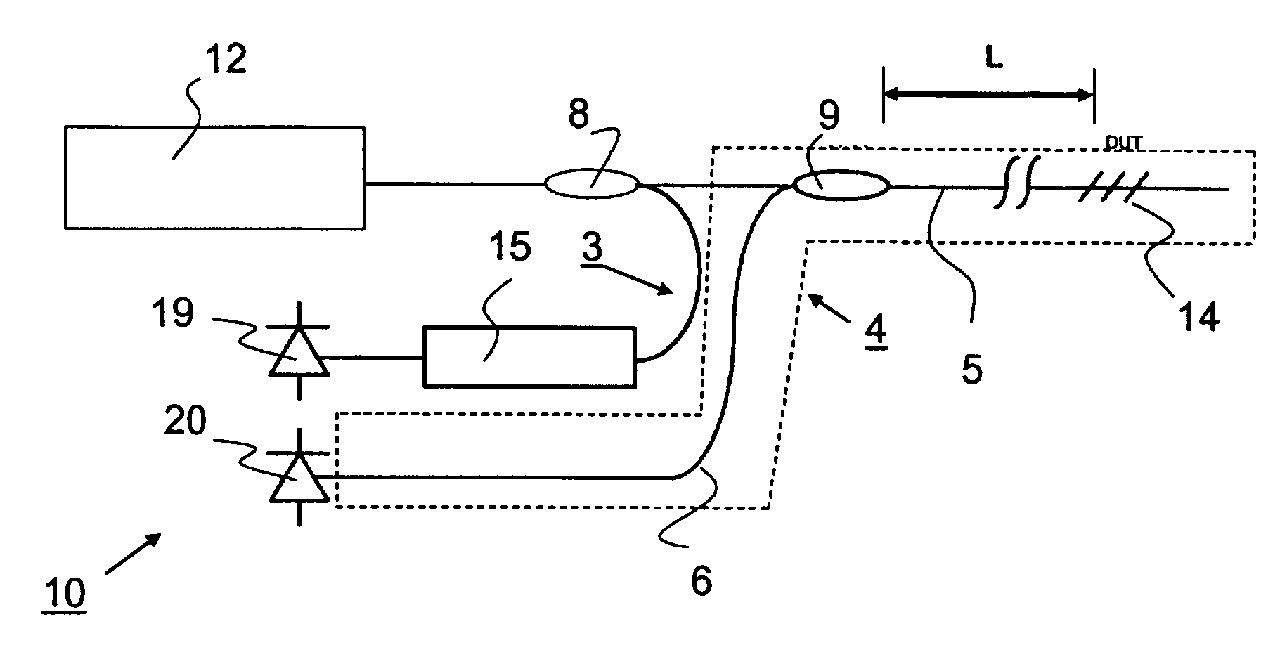
However, as the scan rate or sensor optical path length is increased, delays caused by the finite speed of light in the interconnecting optical fibers will induce a delay in the returned optical signal to the detection circuitry.

Method used


Image

  • Method and apparatus for multiple scan rate swept wavelength laser-based optical sensor interrogation system with optical path length measurement capability
  • Method and apparatus for multiple scan rate swept wavelength laser-based optical sensor interrogation system with optical path length measurement capability
  • Method and apparatus for multiple scan rate swept wavelength laser-based optical sensor interrogation system with optical path length measurement capability

Examples


Embodiment Construction

[0027]“Swept Optical Source” or Swept Wavelength Optical Source” refers to a class of optical sources that output a narrow optical spectrum that can be electrically or mechanically tuned over a relatively wide wavelength range, generally 40 nm or more. Of particular interest for sensing applications are those sources which provide wavelengths within the 1.5 μm wavelength range. Examples of swept wavelength optical sources that can be used in the present invention include swept wavelength fiber lasers, external cavity swept wavelength lasers, distributed Bragg reflector lasers (DBRLs) and broadband sources which in combination with tunable filters provide swept wavelength optical sources. Exemplary external cavity swept wavelength lasers, include among others, those described in U.S. Pat. No. 6,594,289. Broadband sources such as superluminescent LED sources (SLED), as exemplified in U.S. Pat. No. 4,730,331, and superradiant sources, such as exemplified in U.S. Pat. No. 4,637,025, can...


PUM


Abstract

The invention relates to optical sensor measurement methods that use a swept wavelength optical source to determine wavelength shift as well as to optical sensor systems that embody and employ these methods. A variable scan rate swept optical source is used to determine the optical path length from the optical interrogator to the optical sensors being measured. This data can then be used as desired or needed in implementing the sensor or making sensor measurements. In particular the data can be used in the optical sensor system to compensate for potential measurement errors due to the finite speed of light in the optical medium interconnecting optical sensors under test.

Description

CROSS-REFERENCE TO RELATED APPLICATIONS[0001]This application claims priority to U.S. provisional application 60 / 862,756 filed Oct. 24, 2006 which is incorporated by reference in its entirety herein.BACKGROUND OF THE INVENTION[0002]Optical sensing applications are on the rise in such diverse fields as civil structures, aerospace, oil and gas, among many others. Much progress continues to be made on optical sensor technology. As sensors increase in performance and sophistication, an increasingly pressing need emerges for optical measurement equipment (e.g., sensor interrogators, including light source, detectors and wavelength references) to monitor the optical sensors with speed, accuracy and reliability over a variety of physical and environmental conditions.[0003]Although sensor applications vary, the following sensor interrogator requirements are common for many applications. Interrogators should provide accurate and reliable, low noise wavelength measurements (preferably + / −2 to...

Claims


Application Information

Patent Timeline
Patent Type & Authority Patents(United States)
IPC IPC(8): G01J1/04
CPCG01D5/35303G01M11/3145G01M11/3127G01D5/35316
Inventor HABER, TODD C.MOCK, JOEL L.VOLCY, JERRY
Owner LUNA INNOVATIONS
Learn More