Drive circuit, display device, and driving method
a drive circuit and display device technology, applied in the field of drive circuits, can solve the problems of difficult to realize this value, deformation or change in quality, cracks in a portion of electro conductive thin film 3004 locally broken, etc., and achieve the effect of decreasing the current flowing in a moment and increasing the driving energy for driving
- Summary
- Abstract
- Description
- Claims
- Application Information
AI Technical Summary
Benefits of technology
Problems solved by technology
Method used
Image
Examples
example 1
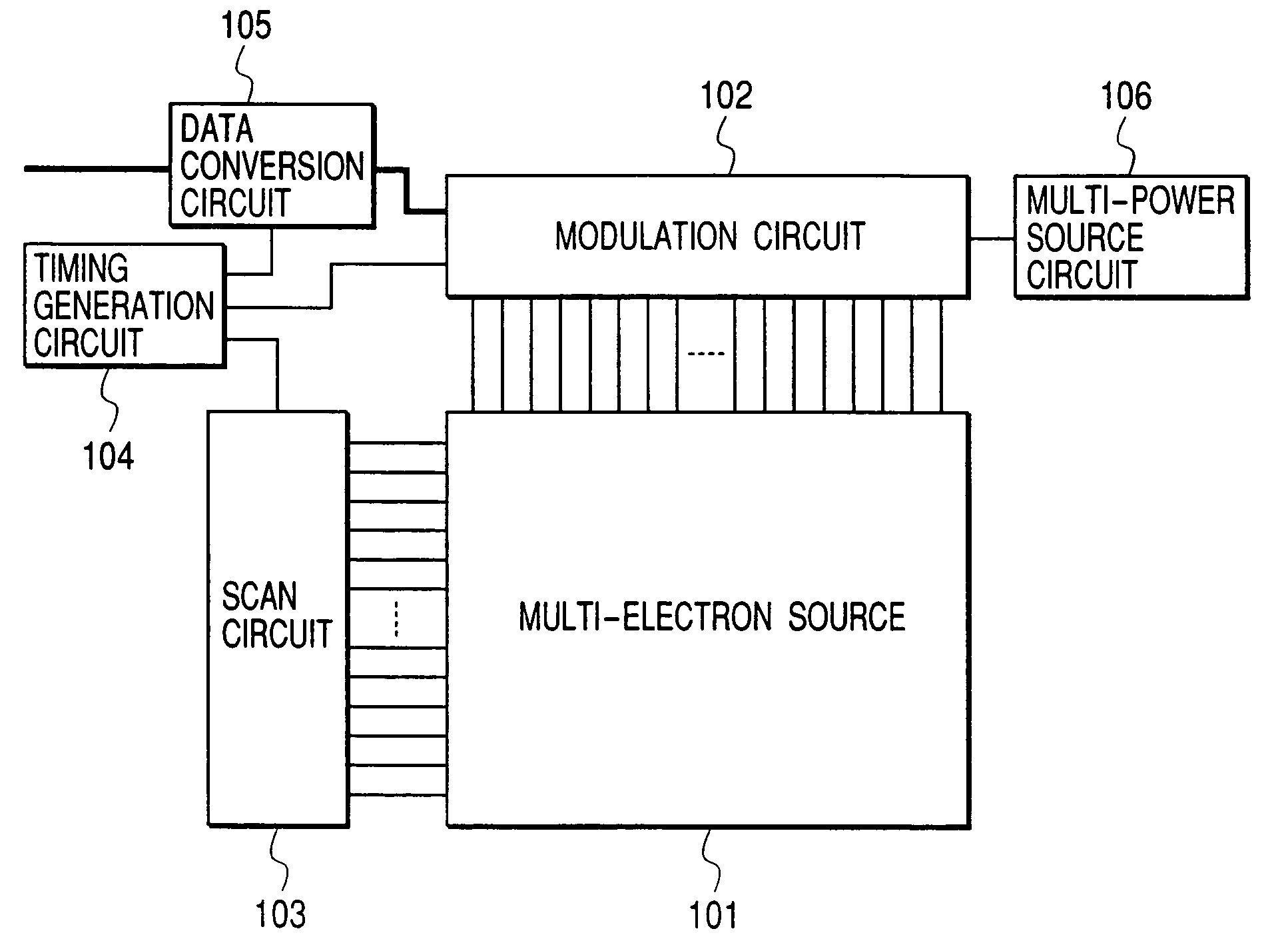
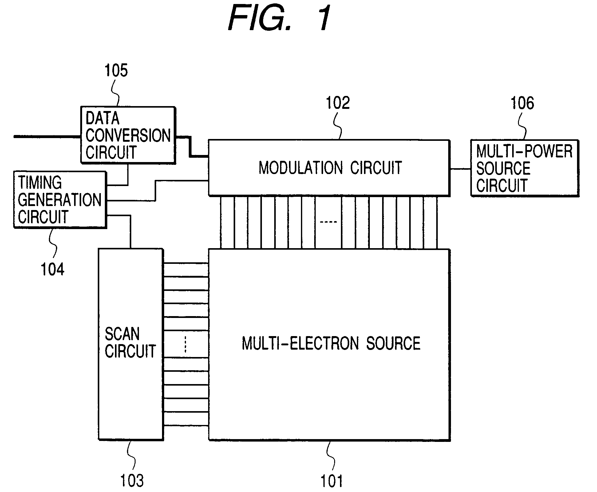
[0161]FIG. 1 is a block diagram of a multi-electron source drive circuit according to an example of the present invention. This figure shows a multi-electron source 101, a modulation circuit 102, a scan circuit 103, a timing generation circuit 104, a data conversion circuit 105, and a multi-power source circuit 106. A multi-electron source 101 is driven in this structure. As shown in FIG. 34, the multi-electron source 101 comprises an electron source (electron emission device) 1 provided in an intersection of row-directional wiring 2 and column-directional wiring 3. As an electron source, although the SCE type, FE type, and MIM type electron emission device are known as described above, in this Example, the SCE type electron emission device was used.
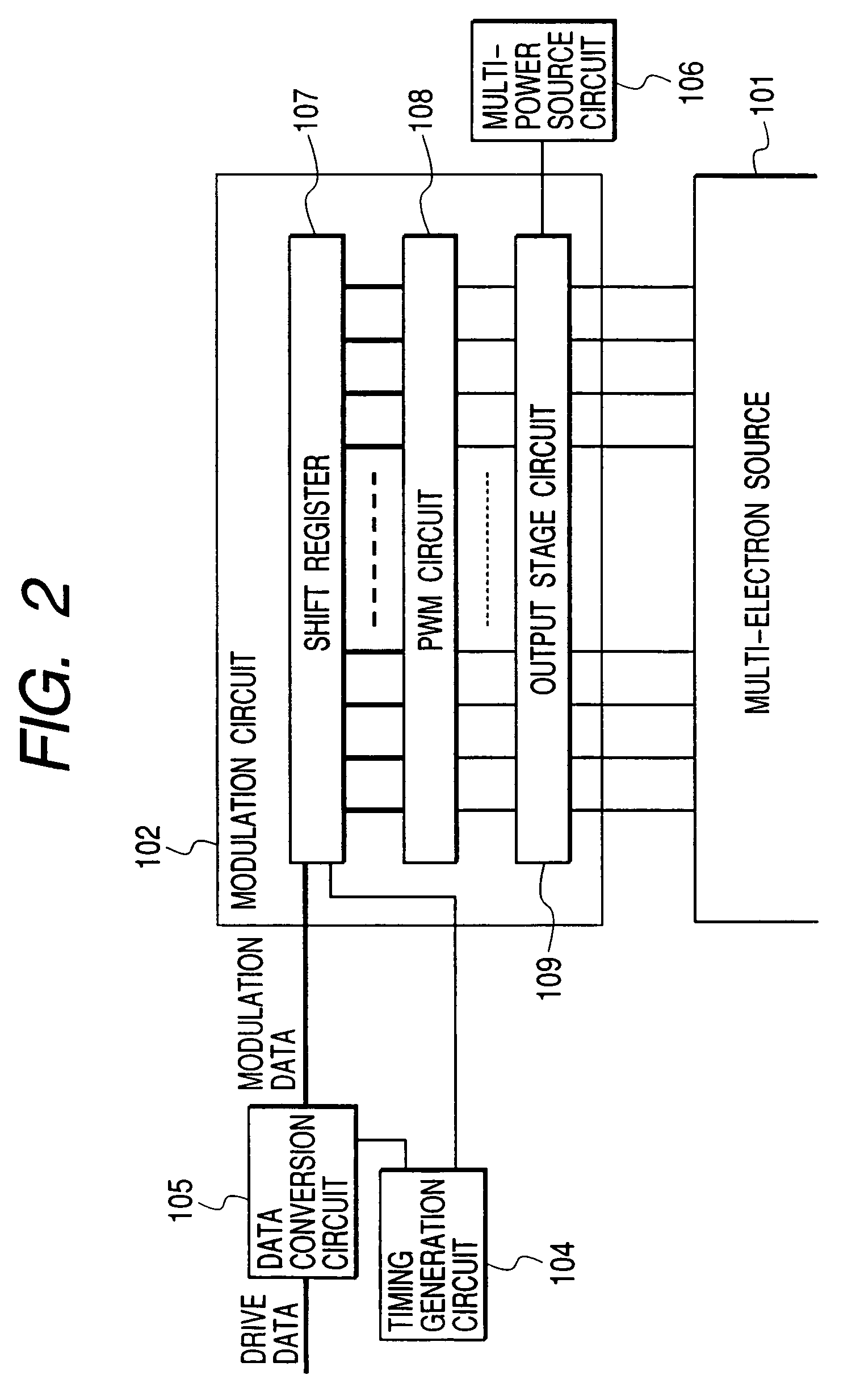
[0162]The data conversion circuit 105 converts drive data, used for driving the multi-electron source 101 from the external, into a format suitable for the modulation circuit 102. The modulation circuit 102 is connected to the column-dir...
example 2
[0188]FIG. 18 shows another example of V14 waveforms. Driving waveforms in FIG. 7 show an example in the case of setting respective drive level potentials V1, V2, V3, and V4 so that a ratio of luminescence intensity might be set to 1:2:3:4. In an LED or an electron emission device, since luminescence intensity is proportional to a drive current in general, hereafter, this is called a current equal dividing method. On the other hand, FIG. 19 shows the case that it is determined to make a ratio of V1, V2, V3, and V4 be 1:2:3:4, i.e., to make potential differences V4−V3, V3−V2, V2−V1, and V1−V0 (reference potential V0 of a driving waveform was made the same as a drive threshold of a device also here) fixed, and hereafter, this is called a voltage equal dividing method. FIG. 19 shows the voltage / current (luminescence intensity) in the voltage equal dividing method.
[0189]In FIG. 18, a reverse unit driving waveform block in an N-th gradation denotes differential from a (N−1)-th gradation....
example 3
[0193]FIG. 21 shows an example of Vn driving waveforms. This waveform is for performing driving with a waveform where a level of a driving waveform of data N is made to be k (k is an integer that is one or more, and less than n) when luminance brightness data consists of R bits and luminance brightness data is approximately 0R) (k / n−1). In the driving waveform in FIG. 8, if the number of unit drive blocks (the number of slots) of the level k of the driving waveform in an (n−1)-th gradation becomes 3 by adding a unit drive block to a driving waveform in an (n−2)-th gradation when a level k is three or less, a unit drive block with a level of k+1 is added to a driving waveform in the following n-th gradation. However, in driving waveforms in FIG. 21, a level (level) is not carried until the number of unit drive blocks with a level of 1 (level 1; the minimum level) reaches a predetermined maximum number S (in this Example, 259) when increasing gradation, but when the number reaches the...
PUM
 Abstract
Description
Claims
Application Information
 - R&D
- Intellectual Property
- Life Sciences
- Materials
- Tech Scout
- Unparalleled Data Quality
- Higher Quality Content
- 60% Fewer Hallucinations
Browse by: Latest US Patents, China's latest patents, Technical Efficacy Thesaurus, Application Domain, Technology Topic, Popular Technical Reports.
© 2025 PatSnap. All rights reserved.Legal|Privacy policy|Modern Slavery Act Transparency Statement|Sitemap|About US| Contact US: help@patsnap.com


