Supercharge Your Innovation With Domain-Expert AI Agents!

Los beat detector

a detector and beat technology, applied in the field of timing elements in optical networking equipment, can solve problems such as loss of signal, failure conditions, and inability to aid in maintaining the hard edges of pulses

Active Publication Date: 2009-08-25
CIENA
View PDF4 Cites 2 Cited by
  • Summary
  • Abstract
  • Description
  • Claims
  • Application Information

AI Technical Summary

Benefits of technology

The present invention provides a beat detector for indicating drift in a recovered clock signal. This detector can be used in optical networking equipment to quickly detect and switch to a reference clocking signal when there is a loss of signal. The detector uses a multiplier, a trigger, a window detector, and a filter to generate a signal indicative of drift in the recovered clock signal. This allows for a faster and more accurate detection of loss of signal, which can improve the reliability and stability of optical networking equipment.

Problems solved by technology

Although amplifiers can be used to address the loss of signal amplitude, they do not aid in maintaining the hard edges of pulses.
In conventional synchronous systems such as SONET and Optical Transport Network (OTN) repeaters, failure conditions can occur and have catastrophic results.
Fiber interruptions and line cuts, as well as other events causing an unplanned termination of service can result in a loss of signal.
This propagation of a transient generates a cascade of element failures, with each element passing the failure-inducing transient to the next element.
When a sudden interruption to a pulse train transmitted on an optical fiber occurs, the receiver clock recovery fails and generates a transient.
Without fast detection of a loss of signal, the failure will propagate downstream.
However, no description of how to implement rapid transient detection is provided.

Method used


Image

  • Los beat detector
  • Los beat detector
  • Los beat detector

Examples


Embodiment Construction

[0022]Generally, the present invention provides a method and system for detecting loss of signal in optical repeaters and other similar environments using frequency deltas.

[0023]In the following description, for purposes of explanation, numerous details are set forth in order to provide a thorough understanding of the present invention. However, it will be apparent to one skilled in the art that these specific details are not required in order to practice the present invention. In other instances, well-known electrical structures and circuits are shown in block diagram form in order not to obscure the present invention. For example, specific details are not provided as to whether the embodiments of the invention described herein are implemented as a hardware circuit, firmware, or a combination thereof.

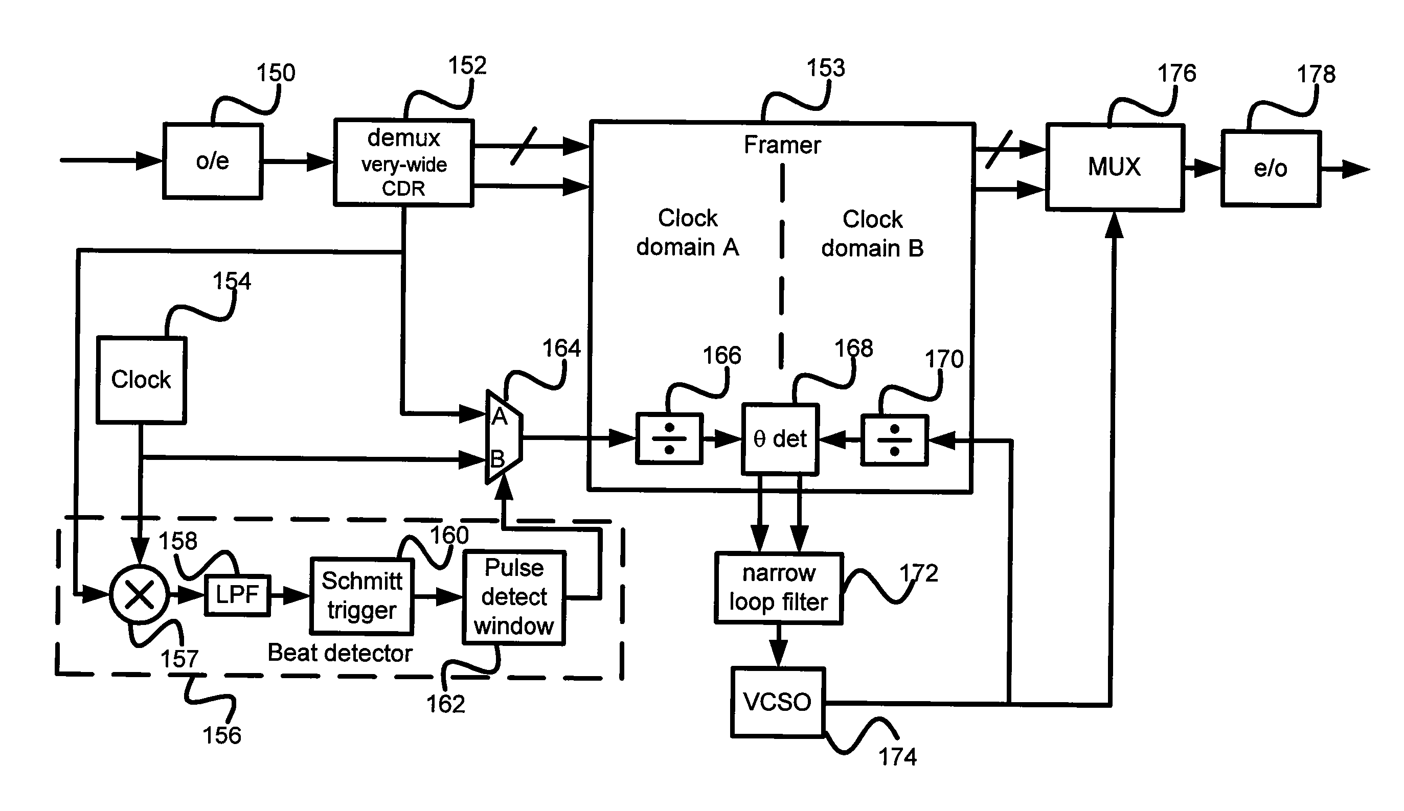
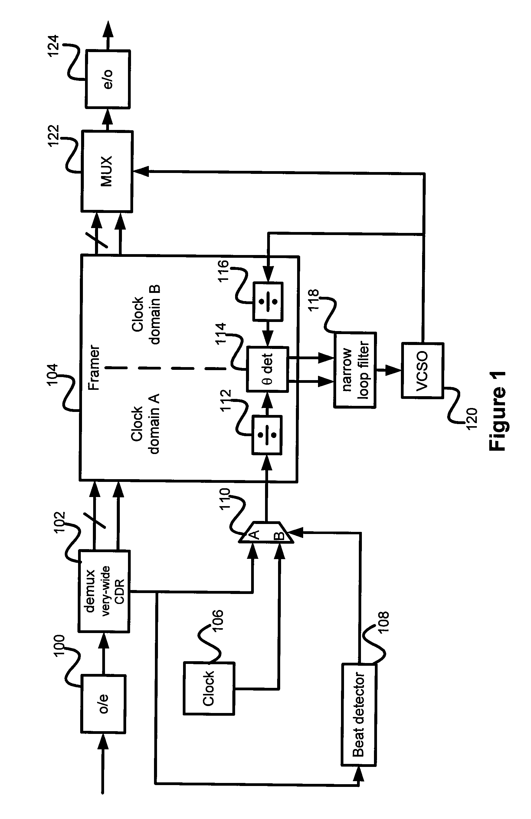
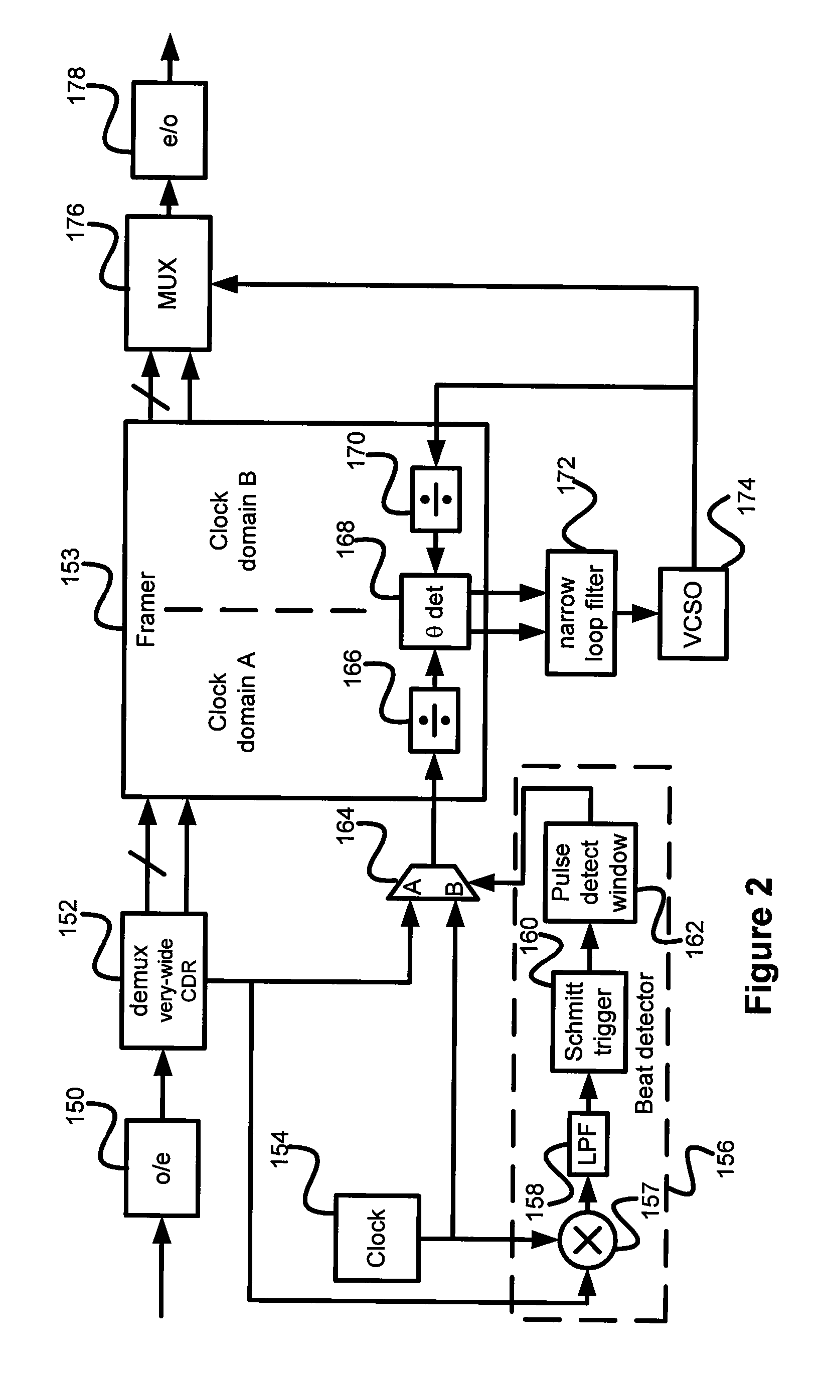
[0024]FIG. 1 presents a block diagram of an optical regenerator. An optical signal is received by optical to electrical converter 100, where it is transferred to the electrical domain....


PUM


Abstract

A loss of signal beat detector makes use of multiplication of a local clock signal and a recovered clock signal to obtain frequency deltas used to indicate loss signal. Through a hardware implementation, a high speed detection is offered, allowing changeover from the recovered clocking signal to the local clock signal when loss of signal is detected to prevent the transmission of a timing transient to downstream nodes.

Description

FIELD OF THE INVENTION[0001]The present invention relates generally to timing elements in optical networking equipment. More particularly, the present invention relates to detecting a loss of signal in an optical network quickly enough to avoid propagation of a large timing transient.BACKGROUND OF THE INVENTION[0002]Optical transmission networks are favored in telecommunications due to the increase in bandwidth that they provide in comparison to traditional metal cable networks. Fiber optic channels are used as the transmission medium for optical signals, commonly optical pulse trains. As a transmitted signal propagates, it degrades due to a number of factors including absorption in the fiber channel.[0003]Although amplifiers can be used to address the loss of signal amplitude, they do not aid in maintaining the hard edges of pulses. The hard edges of the pulses are used by optical elements in a clock recovery process. To ensure that signal degradation does not result in an unrecove...

Claims


Application Information

Patent Timeline
Patent Type & Authority Patents(United States)
IPC IPC(8): H04B10/08H04B17/00
CPCH04B10/299H04J3/14H04J3/0688H04J3/0638
Inventor FIFER, VINCENT
Owner CIENA
Features
  • R&D
  • Intellectual Property
  • Life Sciences
  • Materials
  • Tech Scout
  • Unparalleled Data Quality
  • Higher Quality Content
  • 60% Fewer Hallucinations
Learn More