Tool head for attaching an electrical conductor on the contact surface of a substrate and method for implementing the attachment

a technology of electrical conductors and tool heads, which is applied in the direction of manufacturing tools, soldering devices, auxillary welding devices, etc., can solve the problems of increasing manufacturing time and production costs, and affecting the production efficiency of tools

Inactive Publication Date: 2009-09-01
ROBERT BOSCH GMBH
View PDF21 Cites 4 Cited by
  • Summary
  • Abstract
  • Description
  • Claims
  • Application Information

AI Technical Summary

Benefits of technology

[0013]According to an advantageous embodiment it is provided in this context that the vibration conductor is secured on the converter and freely projects beyond it, the vibration exciter being held on the vibration conductor, in particular. No furthe

Problems solved by technology

The wedge side of the bond is then more difficult to produce than the ball side.
The alignment of the bonding tool with respect to the extension of the conductor in the region of the contact point requires additional displacement movements of the tool head, thus causing a lo

Method used


Image

  • Tool head for attaching an electrical conductor on the contact surface of a substrate and method for implementing the attachment
  • Tool head for attaching an electrical conductor on the contact surface of a substrate and method for implementing the attachment

Examples


Embodiment Construction

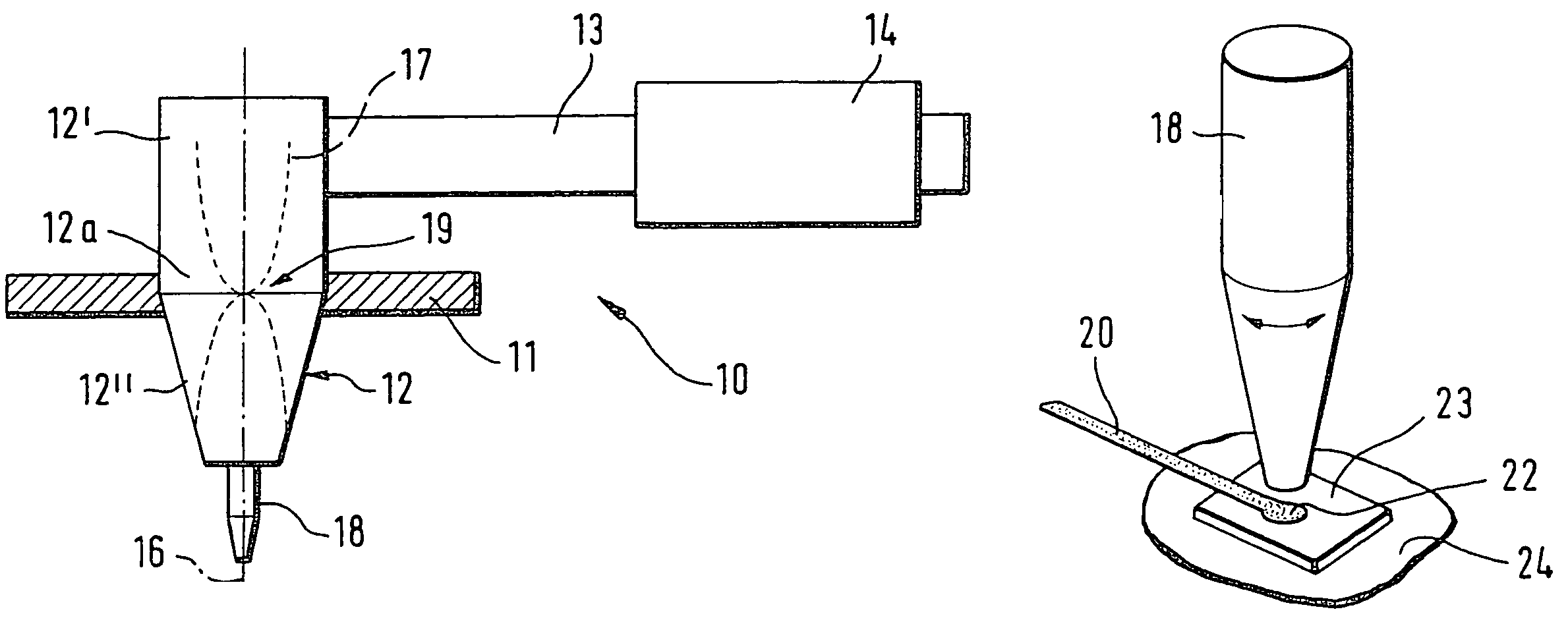
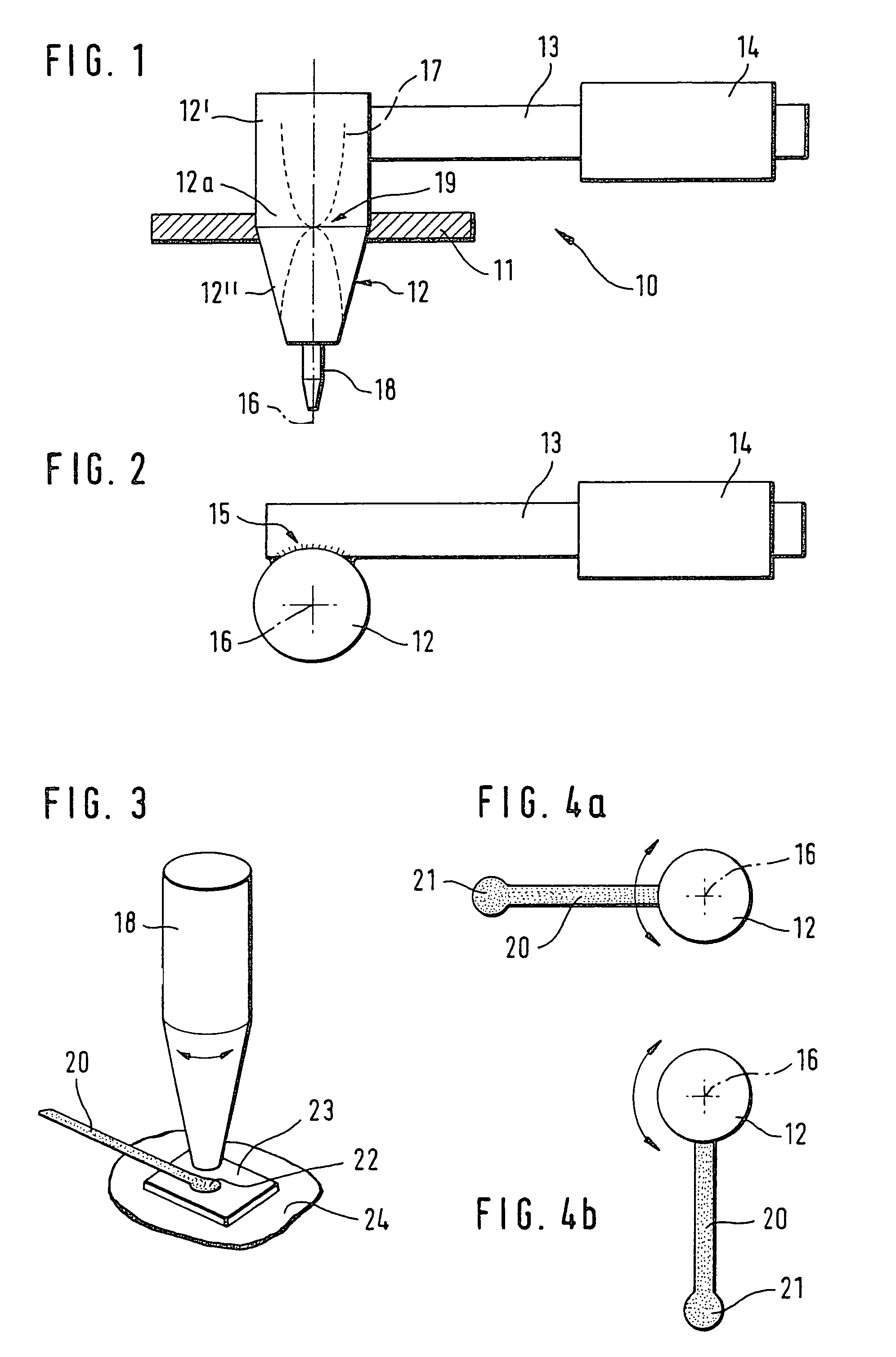
[0020]FIGS. 1 and 2, in a side view and a plan view, show a preferred specific embodiment of a tool head configured according to the present invention, which in this case is denoted overall by reference numeral 10. Tool head 10 has a converter 12, which is held on a tool support 11. Tool support 11 encloses converter 12 in circumferential manner. Converter 12 may be secured on tool support 11 by shrink-fitting, for example. Provided in the upper region of converter 12 is a vibration conductor 13, which is joined to converter 12 via a hard-solder or welding connection 15. Vibration conductor 13 has a rod or tubular design and is secured laterally on the outside of, i.e., tangentially to, converter 12. A vibration exciter 14 is arranged in the region of the free end of vibration conductor 13. Vibration exciter 14, which is embodied as a piezo-crystal body, for example, is able to be excited to linear vibrations of a specified or desired frequency in the ultrasonic range by an electric...


PUM

PropertyMeasurementUnit
Pressureaaaaaaaaaa

Abstract

A tool head for attaching an electrical conductor on the contact surface of a substrate, comprising a vibration exciter for generating linear ultrasonic vibrations; a bonding tool that is able to contact the contact surface and/or the conductor, a contact pressure being able to be applied to the conductor in the direction of the contact point via the bonding tool, and the conductor is able to be welded onto the contact point with the aid of the ultrasonic vibrations able to be transmitted to the contact point and/or the conductor in this manner; and a vibration conductor absorbing the linear ultrasonic vibrations of the vibration exciter; a converter being provided between the vibration conductor and the bonding tool to convert the linear vibrations into radial vibrations in such a way that the bonding tool is able to be incited to rotary vibrations.

Description

BACKGROUND INFORMATION[0001]It is known that electrical conductors must be attached at appropriate contact points on substrates, such as circuit boards, micro-controllers and microprocessors, in order to establish electrical connections to some other contact point.[0002]An electrical conductor is often attached by so-called bonding, which is understood to mean that a continuous material connection between the contact point and the electrical conductor is produced by ultrasonic friction welding. Using selected guidance, a tool head then guides the electrical conductor along a specified path curve to the second contact point, where it is attached in the same manner and then cut off from the supply of the electrical conductor, thereby producing an electrical connection of two contact points of a subassembly, such as a printed board assembly of a control device.[0003]Two basic types of bonding connections are known. In so-called ball bonding, prior to attaching the electrical conductor,...

Claims


Application Information

Patent Timeline
IPC IPC(8): B23K1/06H01L21/60H01L21/607H01R43/02H05K3/32
CPCH01L24/78H01R43/0207H01L2224/78302H01L2924/00014H01L2224/78822H01L2224/85205H01L2224/85206H01L2924/01004H01L2924/01082H05K3/328H01L2924/01005H01L2924/01006H01L2924/01033H01L2224/48H01L2224/45099
Inventor REINOLD, MANFREDKADEN, THOMASBRINKMANN, DIRK
Owner ROBERT BOSCH GMBH
Why Eureka
Try Eureka