Three phase inverter control circuit detecting two phase currents and deducting or adding identical ON periods

a control circuit and inverter technology, applied in process and machine control, electronic commutators, instruments, etc., can solve the problems of reducing the size and reinforcement of vibration-proof properties, unable to make shortening effects available, and unable to achieve shortening effects, so as to ensure increase the shortening effect of carrier cycles. , the current of three phase modulation can be made still smooth

Active Publication Date: 2009-09-01
PANASONIC CORP
View PDF17 Cites 15 Cited by
  • Summary
  • Abstract
  • Description
  • Claims
  • Application Information

AI Technical Summary

Benefits of technology

[0034]The above-configured inverter can extend the ON period of lower arm switching elements without requiring the development of control software of high complexity. This provides a certain period within one carrier in which period current flows in all the three phases of the lower arm switching elements. Consequently, it can detect the current for the three phases with the two current detectors alone (that of the remaining one phase is obtainable through a calculation). Since it reduces an identical ON period with all of the three phases, viz. it does not increase, or decrease, the ON period with parts of phases only (upper arm switching elements), the electric supply period of three phase modulation remains unchanged, so, no current distortion is caused. Furthermore, the carrier cycle shortening effect turns out to be available even in a region where it used to be unavailable, and it makes the current smoother.
[0055]A twelfth inverter in the present invention is that of either one of the first inverter and the fifth inverter, which is to be used on board a vehicle. The inverters for use in such field of application are required to be compact in size and light in weight. So, it is difficult for them to have sufficient considerations on the sound-proof and vibration-proof performance. At the same time, they are required to be tough enough to withstand the vibration of a cruising vehicle. The present inverter, which is compact in size, vibration-proof, and low in the operating noise / vibration, would be advantageous in this field of application.

Problems solved by technology

So, even though there are two electric supply periods in a carrier cycle, eventual number of electric supply periods for each carrier cycle become to be only one, therefore, no carrier cycle shortening effect can be made available.
So, in a certain specific phase the carrier cycle, shortening effect can not be made available.
The conventional methods of detecting the phase current have their own respective problems to be solved.
So, the size reduction and reinforcement of vibration-proof property are the problems to be solved.
Furthermore, because of the bulky size, freedom degree of layout on a printed board is limited.
This complicates software for controlling.
Furthermore, increase or decrease of parts of phases (upper arm switching element) of the ON period brings about a distortion in the current waveform.
This is an adverse factor against noise and vibration.
In a case of a vehicle-mounted electric compressor, however, the space for installation and the allowable weight are limited.
So, installation of a soundproofing device may be difficult.
In addition, the intrusion of vibration into vehicle cabin has to be suppressed to a minimum, however, introduction of a quake isolating device may be almost as difficult by the same reasons.
This complicates the control software.
This is against the downsizing efforts, and power consumption and heat generation by the shunt resistors have to be considered too.

Method used


Image

  • Three phase inverter control circuit detecting two phase currents and deducting or adding identical ON periods
  • Three phase inverter control circuit detecting two phase currents and deducting or adding identical ON periods
  • Three phase inverter control circuit detecting two phase currents and deducting or adding identical ON periods

Examples


first exemplary embodiment

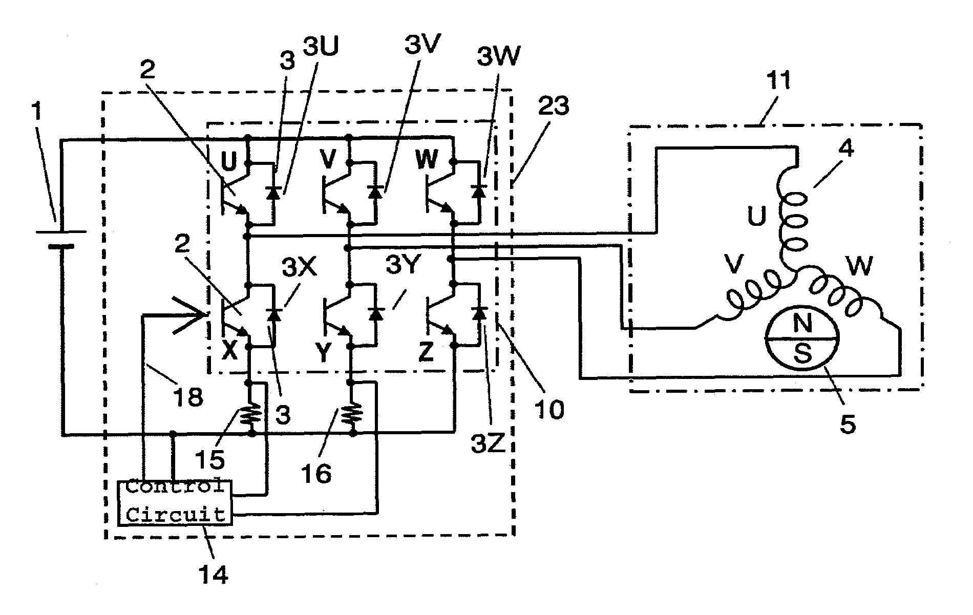
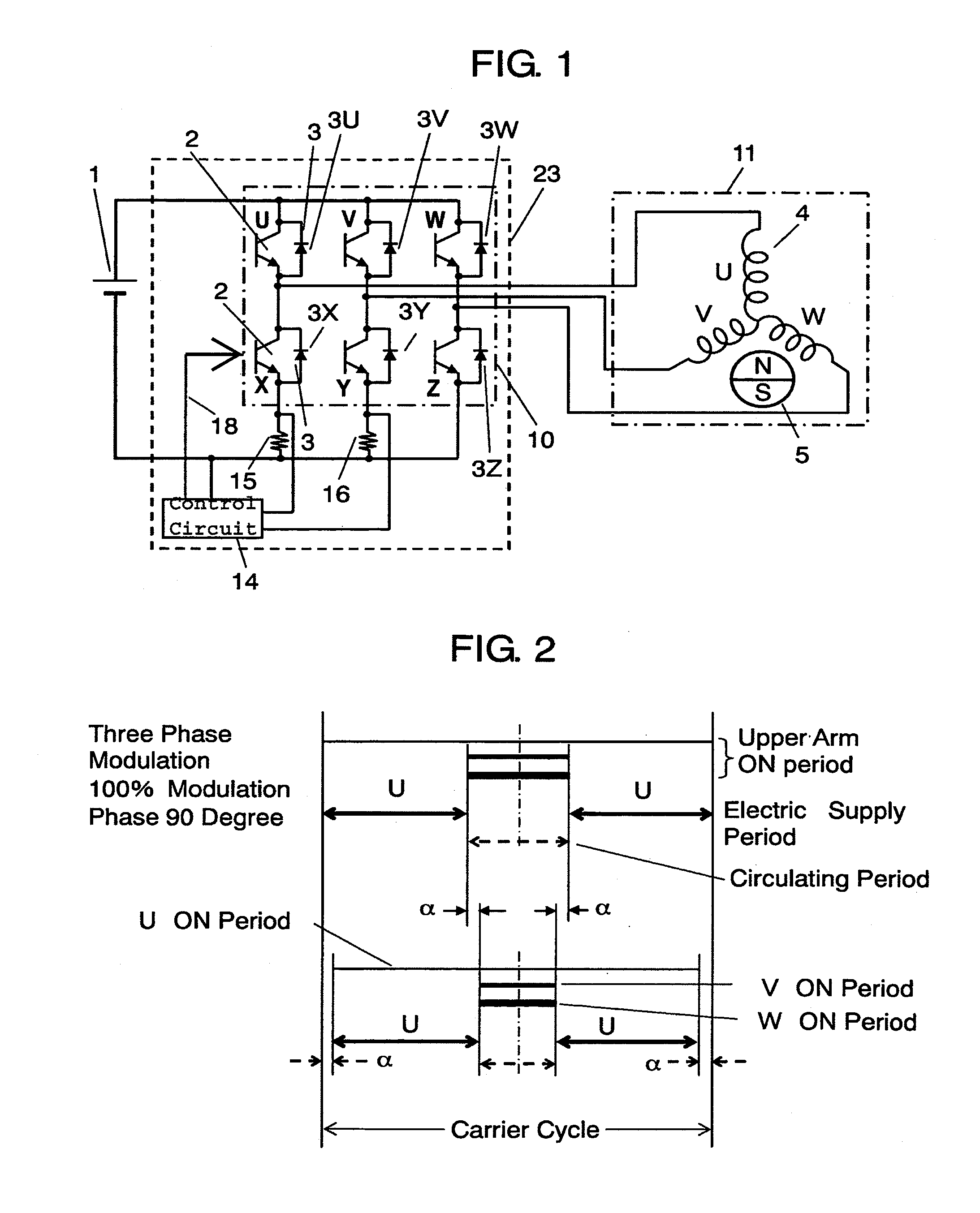
[0084]FIG. 1 shows an electrical circuit diagram of inverter 23 and its periphery in accordance with a first exemplary embodiment of the present invention. As compared with that of the background art shown in FIG. 22, shunt resistor 17 has been eliminated and control circuit 13 has been replaced with control circuit 14. Other portion of the circuit remains the same as that shown in FIG. 22, and the same symbols are used for the respective corresponding items.

[0085]Control circuit 14 is connected with upper arm switching elements U, V, W and lower arm switching elements X, Y, Z, through connection lines 18, and controls respective switching elements. In a case where an IGBT or a power MOS FET is used as the switching element, the control circuit controls the gate voltage; where a power transistor is used, it controls the base current.

[0086]In FIG. 24, at phase 90 degrees, current flows in the lower arm in two phases (phase V, phase W) only. Likewise, at phase 210 degrees, in phase W ...

second exemplary embodiment

[0107]Characteristic charts of an inverter in accordance with a second embodiment of the present invention are shown in FIG. 6 through FIG. 9. Electrical circuit of the inverter and periphery remains the same as that of the first embodiment, which is shown in FIG. 1.

[0108]The upper part of FIG. 6 shows the situation of FIG. 21 at phase 90 degrees as it is. It is shown in the lower part that identical ON period 28 is deducted from ON periods of the respective upper arms U, V, W, and the length of upper circulating period (2δ) has been made to be equal to that of the lower circulating period (2δ=δ+δ).

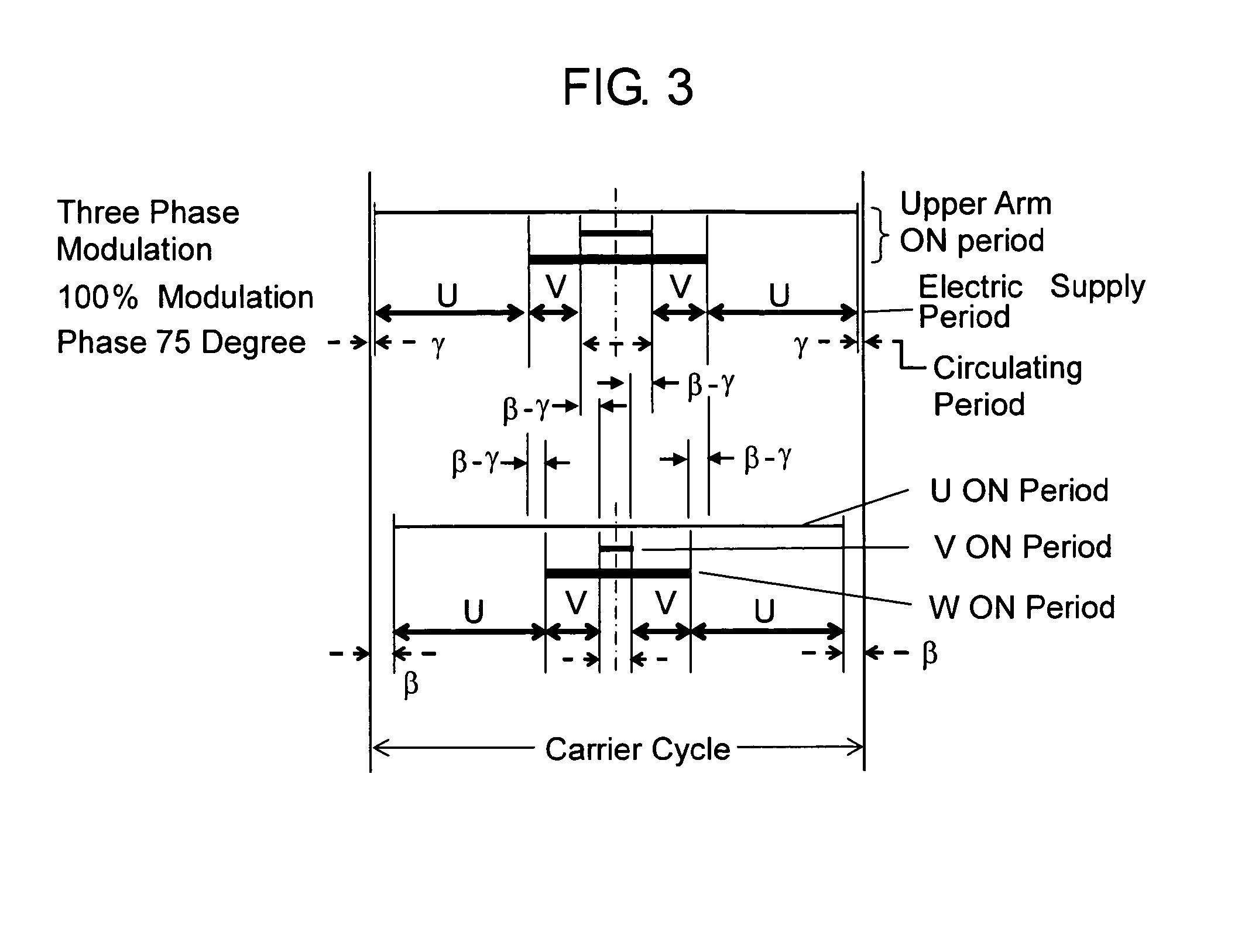
[0109]Likewise, FIG. 7 shows the situation at phase 75 degrees. It is shown that identical ON period 2*(τ−γ) is deducted from ON periods of the respective upper arms U, V, W, and the length of upper circulating period (2τ) has been made to be equal to that of lower circulating period (2τ=τ+τ).

[0110]Accordingly, since the intervals among the electric supply periods become equal in the carr...

third exemplary embodiment

[0113]FIG. 10 shows electric compressor 40 and inverter 23. The inverter 23 is mounted closely to the right side of the compressor 40. Compression mechanism 28, motor 11, or the like are placed in metal container 32.

[0114]Refrigerant is sucked-in from intake 33, and compressed by compression mechanism 28 (a scroll unit, in this example) which is driven by motor 11. When the compressed refrigerant passes through motor 11, the refrigerant cools motor 11, and then is discharged from outlet 34.

[0115]To facilitate the mounting to electric compressor 40, inverter 23 is housed in casing 30. The inverter's circuit portion 10, which is the source of heat generation, is cooled by low pressure refrigerant via low pressure piping 38. In order to avoid dewing, inverter 23 is disposed below intake pipe 38 so that ambient temperature of inverter circuit 10 is also lowered for making a temperature difference smaller.

[0116]Terminal 39, which is coupled with the winding of motor within inside of elec...


PUM


Abstract

A small and highly vibration-proof inverter capable of detecting a phase current without requiring the development of complicated control software and without causing any current distortion is provided. Shunt resistors (15, 16) serving as a kind of current detector are provided, respectively, between lower arm switching elements X, Y, Z) in only two phases—and the minus side of a DC power supply. An identical ON period is reduced from the ON periods of upper arm switching elements (U, V, W) in the carrier cycle entirely for three phases. Consequently, phase current is detected for the two phases provided with the shunt resistors (15, 16). The inverter can detect the phase current without complicating the control software and without causing any current distortion, by controlling inverter circuit (10) with control software incorporated in control circuit (14) through connection lines (18).

Description

TECHNICAL FIELD[0001]The present invention relates to a three phase PWM (Pulse Width Modulation) inverter provided with a phase current detection means.BACKGROUND ART[0002]Conventionally, in inverters which drive sensorless DC brushless motors with a PWM sinusoidal drive method, a method of detecting two currents out of the three output lines of the inverter is known (Japanese Patent Unexamined Publication No. 2000-333465, FIG. 2, page 9, for example).[0003]The circuit for the above detecting method is described below. FIG. 11 shows the inverter and electrical circuits around it. To control circuit 7 of inverter 20, the phase U current is input from current sensor 8, and the phase W current is input from current sensor 9. Based on the values of these two currents, the phase V current is calculated by applying Kirchhoff's current law at the neutral point of stator winding 4. Using these phase U, phase V and phase W current values, induction voltage induced at stator winding 4 by magn...

Claims


Application Information

Patent Timeline
Patent Type & Authority Patents(United States)
IPC IPC(8): H02M7/5387
CPCB60H1/00428H02P6/18H02M7/53871H02M2001/0009Y02T10/88H02M7/5395H02M1/0009
Inventor GOTO, NAOMI
Owner PANASONIC CORP
Why Eureka
Try Eureka