
System and method for vacuum chamber leak detection

a vacuum chamber and leak detection technology, applied in liquid/fluent solid measurement, machines/engines, instruments, etc., can solve the problems of large leakage in the chamber, small leakage may arise from more subtle failures, and the effect of material processing within the chamber can be detrimental

Active Publication Date: 2009-09-15
PIVOTAL SYST CORP
View PDF4 Cites 32 Cited by
  • Summary
  • Abstract
  • Description
  • Claims
  • Application Information

AI Technical Summary

Problems solved by technology

Where one or more of these components fails to function as expected, the effect on materials being processed within the chamber can be detrimental.
Large leaks in a chamber may be caused by such things as a failed valve or stuck MFC.
By contrast, smaller leaks may arise from more subtle failures, such as a cracked seal, or a valve not fitted sufficiently tightly.
Such smaller leaks are often difficult to detect, and may go undetected for quite some time.
However, changed composition of gas in the chamber resulting from such smaller leaks can be sufficient to ruin the wafer being processed.
The near-invisibility of small leaks, combined with their effect on sensitive recipes, renders such small leaks a significant problem.
Still another type of problem may arise where gas is introduced into the environment of the chamber through a “virtual leak”.
One example of such a virtual leak occurs due to outgassing from materials already present within the chamber, such as residue from previous processes.
The gas resulting from such a virtual leak can also adversely affect the reliability of processes occurring within a chamber.

Method used


Image

  • System and method for vacuum chamber leak detection
  • System and method for vacuum chamber leak detection
  • System and method for vacuum chamber leak detection

Examples


example 1

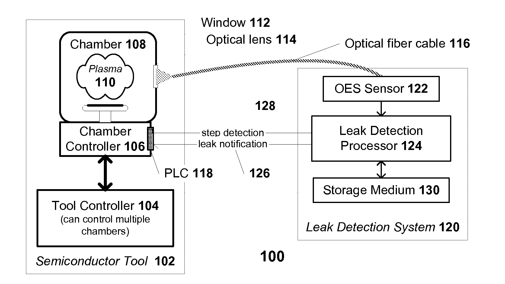
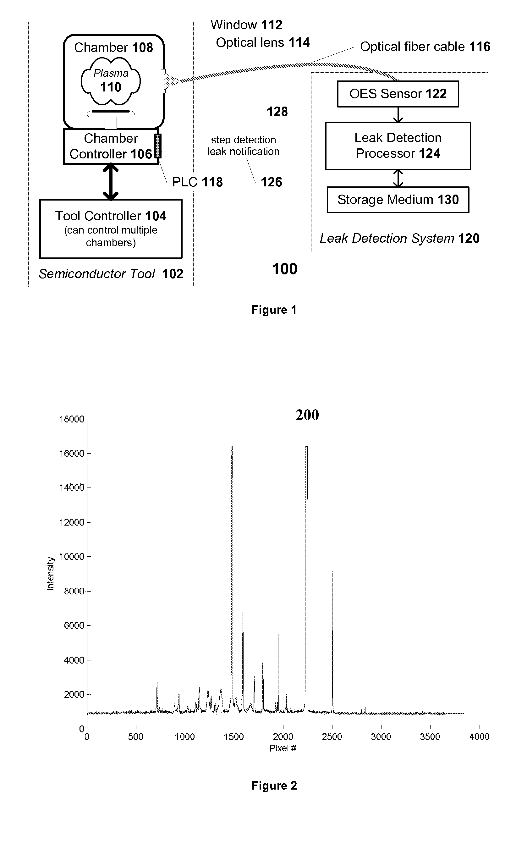
[0093]Leakage of a low pressure chemical vapor deposition (LPCVD) chamber was tested. The step of interest involved a Nitrogen based recipe not containing any Argon, and was performed at a pressure of about 50 mTorr. Because air in the surrounding environment includes trace amounts of Argon, and because Argon exhibited visible peaks in the spectrum for this recipe, the presence of Argon within the chamber during this step was selected to indicate a leak.

[0094]Detection of the step of interest was based upon an analog voltage. Specifically, the programmable logic controller of the chamber was configured to output a 24V DC current when the recipe step of interest was being processed, and to output 0V DC current when a recipe of interest was not being processed.

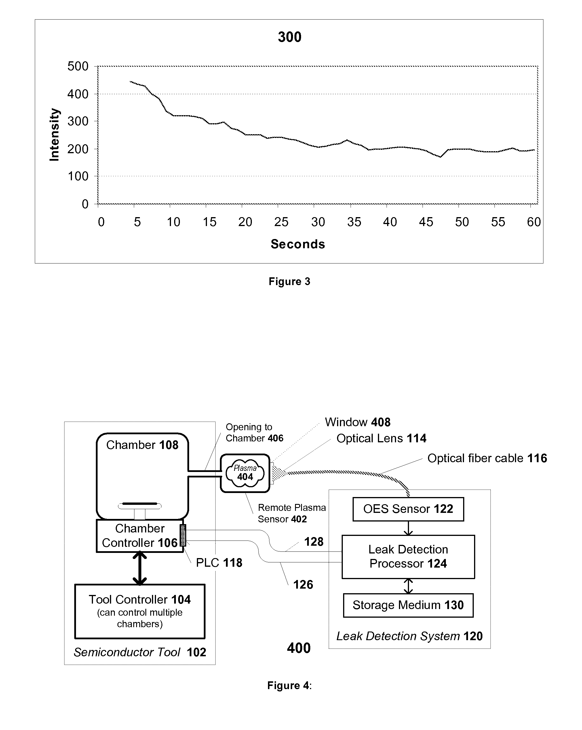
[0095]Data was acquired from the chamber utilizing a remote plasma sensor. The remote plasma sensor was equipped with a HR4000 spectrometer obtained from Ocean Optics Inc., of Dunedin, Fla. The HR4000 was configured with a spect...

example 2

[0100]Leakage of the same low pressure chemical vapor deposition (LPCVD) chamber as mentioned above in EXAMPLE 1, was tested for a different leak. The step of interest involved the same Nitrogen-based recipe, and was performed at a pressure of about 50 mTorr. This chamber exhibited a “virtual” oxygen leak resulting from the outgassing of oxygen due to the reaction of the nitride chemistry with material left on the chamber wall from previous depositions. The virtual leak was harmful to the wafer if the magnitude of the virtual leak surpassed a threshold.

[0101]Detection of the step of interest was based performed in the same manner as in the previous example. Similarly, data was acquired from the chamber utilizing the same remote plasma sensor and optical sensor as in the previous example.

[0102]Wavelength mapping correction was performed by searching for peak that representing elemental Nitrogen as the reference peak. This peak occurred around pixel 2200. Data validation was employed ...


PUM


Abstract

Leaks in a processing chamber, including “virtual leaks” resulting from outgassing of material present within the chamber, may be detected utilizing an optical emission spectroscopy (OES) sensor configured to monitor light emitted from plasma of a sample from the chamber. According to certain embodiments, gas introduced into the chamber by the leak may be detected directly on the basis of its optical spectrum. Alternatively, gas introduced by the leak may be detected indirectly, based upon an optical spectrum of a material resulting from reaction of the gas attributable to the leak. According to one embodiment, data from the OES sensor is received by a processor that is configured to compute a leak detection index. The value of the leak detection index is compared against a threshold to determine if a leak is detected. If the value of the index crosses the threshold, a notification of the existence of a leak is sent.

Description

BACKGROUND OF THE INVENTION[0001]Many types of semiconductor manufacturing equipment include a chamber where processing of the wafers is performed. In certain processes, the chamber is maintained at reduced pressure, and the flow of gases into and out of the chamber is tightly controlled. Examples of elements configured to ensure a controlled flow of gases into such a chamber include but are not limited to mass flow controllers (MFCs), pumps, valves, and seals, which may operate in conjunction to maintain the processing chamber in the desired state. Processes that are sensitive to gas composition may depend on all of these elements working reliably. Where one or more of these components fails to function as expected, the effect on materials being processed within the chamber can be detrimental.[0002]Large leaks in a chamber may be caused by such things as a failed valve or stuck MFC. Such events are generally detectable, and readily corrected by equipment engineers.[0003]By contrast...

Claims


Application Information

Patent Timeline
Patent Type & Authority Patents(United States)
IPC IPC(8): G01F17/00
CPCG01M3/38
Inventor CHUNG, SHERKVENKATESH, MUKUND CHAKRAVARTHYCHOW, PAXTON MING KAICHENG, JIUYITRAN, PAULMONKOWSKI, JOSEPH RAYMOND
Owner PIVOTAL SYST CORP
Learn More