Alternator having Lundell type rotor

a technology of alternators and rotors, which is applied in the direction of stator/rotor bodies, magnetic circuit rotating parts, magnetic circuit shape/form/construction, etc., can solve the problems of difficult to ensure that the welded portion has the same strength as the non-welded portion, the joint ring is fatigued, and the change in the magnetic characteristics of the end can be prevented , the effect of reducing torsion and high tensile strength

Inactive Publication Date: 2009-09-22
DENSO CORP
View PDF9 Cites 27 Cited by
  • Summary
  • Abstract
  • Description
  • Claims
  • Application Information

AI Technical Summary

Benefits of technology

[0015]An object of the present invention is to provide, with due consideration to the drawbacks of the conventional rotor of an alternator, a Lundell type rotor of an alternator which is superior in a vibration proof and in resistance against a centrifugal force and is manufactured at a low cost so as to have a sufficient fatigue life.
[0019]Because no heating process is applied to the ends of the claw pole joint ring, a change in magnetic characteristics of the ends can be prevented. Further, because each turn portion having no seams is attached to the claw poles, the claw pole joint ring having the plurality of turn portions can tightly be attached to the claw poles with high tensile strength. Moreover, the turn portions are independently displaced so as to reduce torsion caused in the claw pole joint ring due to the vibrations and centrifugal force.
[0020]Accordingly, the rotor with the claw pole joint ring is superior in the vibration proof and in resistance against the centrifugal force and can be manufactured at a low cost so as to have a sufficient fatigue life.

Problems solved by technology

However, it is not easy to precisely or uniformly join the ends of the band plate to each other by welding or the like.
Therefore, it is difficult to ensure that the welded portion has the same strength as that of the non-welded portion.
Therefore, the joint ring is fatigued.
Therefore, there is a high probability of heat deterioration occurring in the joint ring.
However, the manufacturing of the rotor is complicated, and a space for the field coil is narrowed.

Method used


Image

  • Alternator having Lundell type rotor
  • Alternator having Lundell type rotor
  • Alternator having Lundell type rotor

Examples


embodiment 1

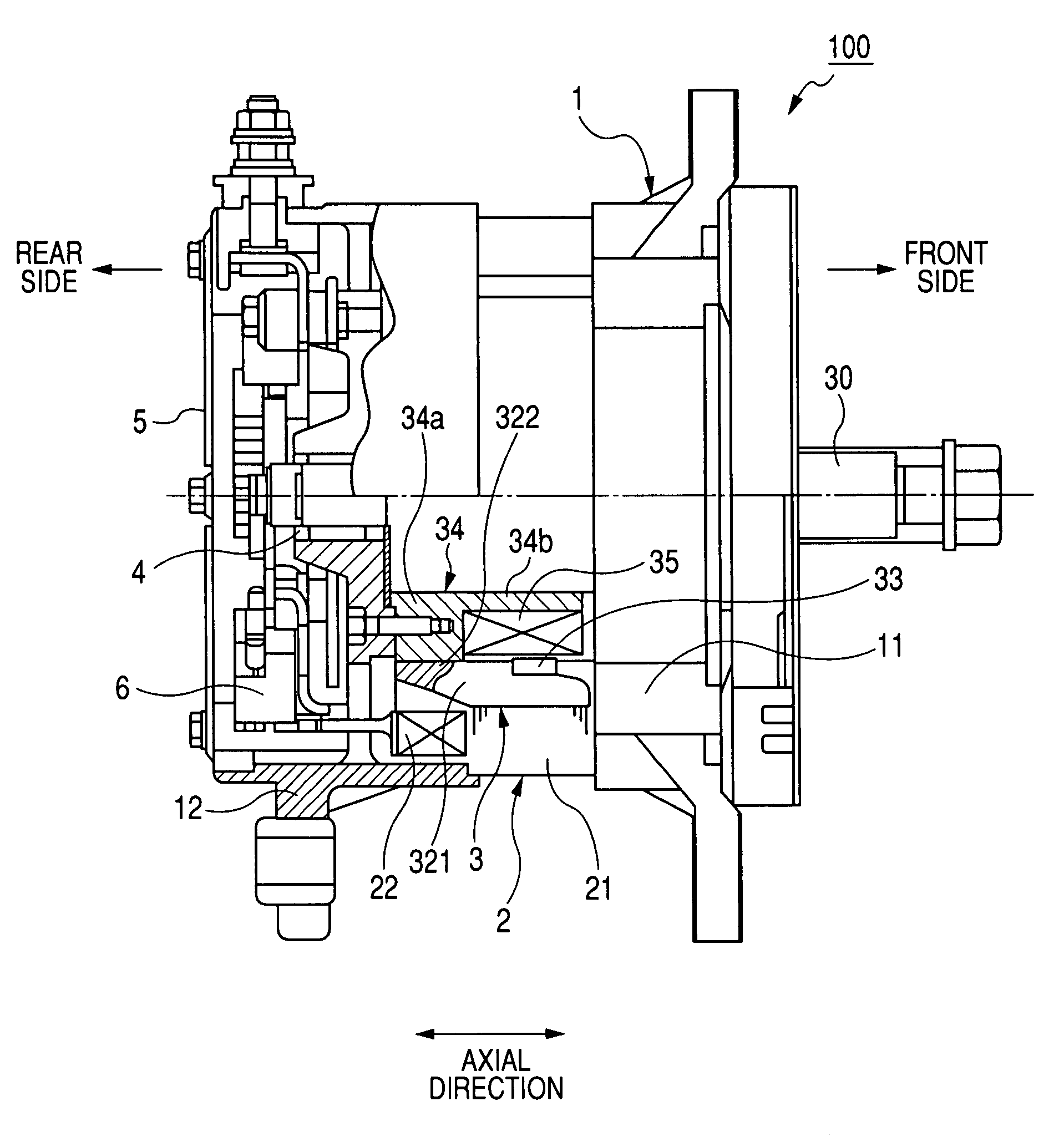
[0035]FIG. 1 is a side view, with portions broken away for clarity and partially in cross-section, of an alternator according to a first embodiment of the present invention.

[0036]As shown in FIG. 1, an alternator 100 mounted on a vehicle has a housing 1, a cylindrical stator 2 disposed in the housing 1, and a Lundell type rotor 3 formed in a columnar shape. The housing 1 has a cup-shaped front housing 11 and a cup-shaped rear housing 12, respectively, disposed on the front and rear sides of the alternator. The housings 11 and 12 hold the stator 2. The stator 2 has a stator core 21 and a stator coil 22 wound around the core 21. The rotor 3 is rotatably disposed in an inner opening of the stator 2 in a radial direction of the alternator 100. The rotor 3 has a rotational shaft 30 rotated in response to a rotational force transmitted from an engine (not shown) of the vehicle. A rear end of the shaft 30 is rotatably held by a bearing 4 of the rear housing 12, and a front end of the shaft...

modification 1

[0061]FIG. 8 is a side view, with portions broken away for clarity, of the joint ring 33 according to the first modification of the first embodiment.

[0062]As shown in FIG. 8, each turn portion of the joint ring 33 may be formed in a circular shape in section. More specifically, the joint ring 33 is formed by spirally bending a long band bar made of a non-magnetic stainless steel and formed in a circular shape in section. Before the band bar is bent, deformation working such as ironing or press working is performed for the band bar. Therefore, portions of the band bar can be substantially flatten so as to be attached to the claw poles 311 and 321 in a wide attaching area.

[0063]Because the deformation working is performed for the band bar, the mechanical strength of the joint ring 33 can be heightened.

modification 2

[0064]FIG. 9 is an exploded view of a portion of the joint ring 33 seen along the radial direction according to the second modification of the first embodiment.

[0065]As shown in FIG. 9, the turn portions 330 of the joint ring 33 may be bent toward the proximal portion of each claw pole at the same position as that of the claw pole in the circumferential direction. More specifically, the turn portions 330 are deformed toward the front side at an area facing each claw pole 311, and the turn portions 330 are deformed toward the rear side at an area facing each claw pole 321.

[0066]Accordingly, the surface of the joint ring 33 attached to each claw pole can be increased in area, so that the joint ring 33 can be attached to the claw poles 311 and 321 with the sufficient joint strength.

Other Modifications

[0067]Various types of known strength heightening processes may be performed for the band steel forming the joint ring 33 to heighten the tensile strength of the joint ring 33. Further, va...


PUM


Abstract

A Lundell type rotor of an alternator has a pole core disposed on an outer side of a field coil in a radial direction of the rotor, and a non-magnetic claw pole joint ring. The pole core has claw poles disposed along a circumferential direction of the rotor at predetermined intervals. Each claw pole extends along an axial direction of the rotor and is magnetized in response to an electric current supplied to the field coil. The joint ring is formed by spirally bending a long band bar in a coil shape and has turn portions disposed along the axial direction. Each turn portion of the joint ring has no seams and is attached to inner side surfaces of the claw poles in the radial direction.

Description

CROSS-REFERENCE TO RELATED APPLICATION[0001]This application is based upon and claims the benefit of priority of the prior Japanese Patent Application 2006-281458 filed on Oct. 16, 2006, so that the contents of which are incorporated herein by reference.BACKGROUND OF THE INVENTION[0002]1. Field of the Invention[0003]The present invention relates generally to a Lundell type rotor of an alternator mounted on a vehicle, and more particularly to the rotor wherein a plurality of claw poles disposed along a circumferential direction of the rotor are joined to a claw pole joint ring to be fixed to one another.[0004]2. Description of Related Art[0005]An alternator used for a vehicle has a cylindrical stator and a columnar rotor disposed in a center space of the stator and generates an alternating current from a rotational force applied to the rotor. The rotor such as a Lundell type rotor has a rotational shaft, a rotor core rotated with the shaft, and a field coil wound on the core. The rot...

Claims


Application Information

Patent Timeline
Patent Type & Authority Patents(United States)
IPC IPC(8): H02K1/22H02K15/02
CPCH02K21/044H02K1/243
Inventor HAMADA, HIROSHI
Owner DENSO CORP
Why Eureka
Try Eureka