Rotary disk laser module

a laser module and rotary disk technology, applied in semiconductor lasers, lighting and heating devices, instruments, etc., can solve the problems of fundamental limitation of the brightness of conventional continuous-wave or quasi-continuous-wave, unavoidable, and inability to fully correct, so as to improve the heat dissipation effect

Active Publication Date: 2009-09-22
BASU SANTANU
View PDF11 Cites 9 Cited by
  • Summary
  • Abstract
  • Description
  • Claims
  • Application Information

AI Technical Summary

Benefits of technology

[0007]In the basic configuration, a mechanical bearing is used to ensure stable motion of the optical disk. However the mechanical bearing may be replaced by a gas or fluid bearing. The rotation of the optical disk allows the regions in space where the incident pump energy is delivered to be separated from the regions in space where the optical radiation is extracted if such separation is needed. The rotation of the optical disk also allows separating the region in space where the heat is being deposited from the regions in space where the heat is being removed. In addition to the improved heat dissipation effect, the rotation of the optical disk allows multiple pump energies and / or multiple optical radiations to be applied and extracted simultaneously.

Problems solved by technology

The waste heat in any solid state laser medium often causes uncorrectable phase aberration in the path of the laser beam due to thermal and stress induced refractive index change.
It imposes fundamental limitation on brightness of a conventional continuous-wave or quasi continuous-wave solid state laser in which the gain medium is stationary.
Such problem is unavoidable and cannot be fully corrected by application of adaptive optics without causing significant power loss.
As mentioned above, the brightness of all these designs is limited by the uncorrectable phase aberration caused by increasing temperature.

Method used


Image

  • Rotary disk laser module
  • Rotary disk laser module
  • Rotary disk laser module

Examples


Embodiment Construction

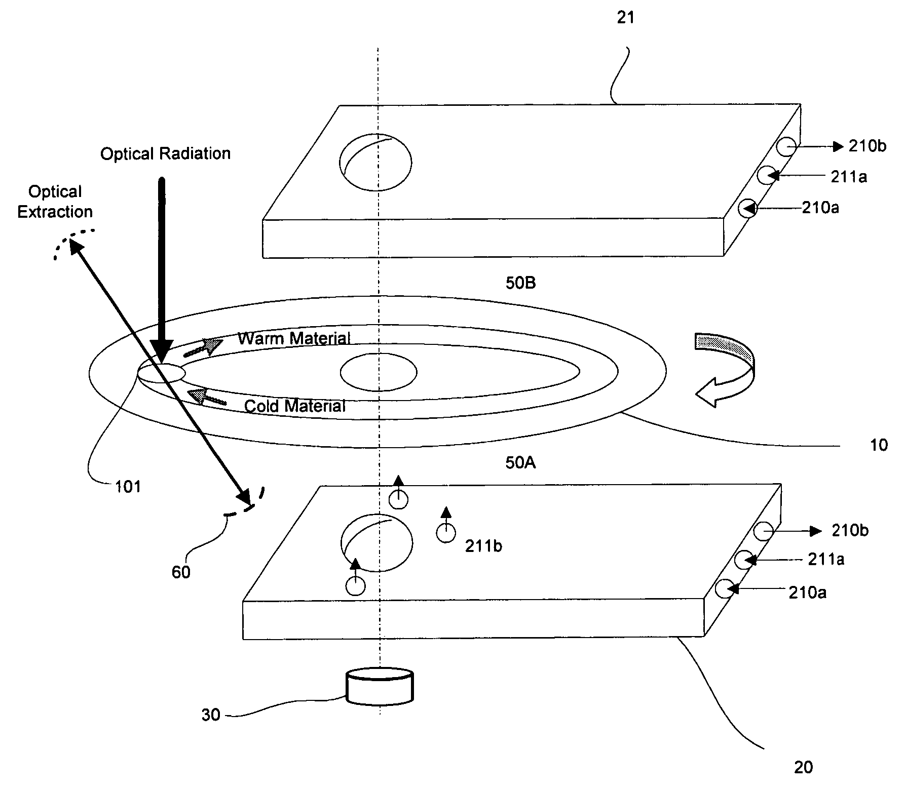
[0022]As discussed above, a rotary disk module as provided can be applied in various devices for many different purposes such as providing gains for laser amplifiers and oscillators, wavelength conversion for nonlinear optics, providing phase modulation in a high-power laser beam, and generating an optical radiation from an electric energy. One of the optical applications is used as an example as follows for explaining and describing the detailed structures and functions of the rotary disk module. However, it will be appreciated that the application of the rotary disk module should not be limited to the optical application.

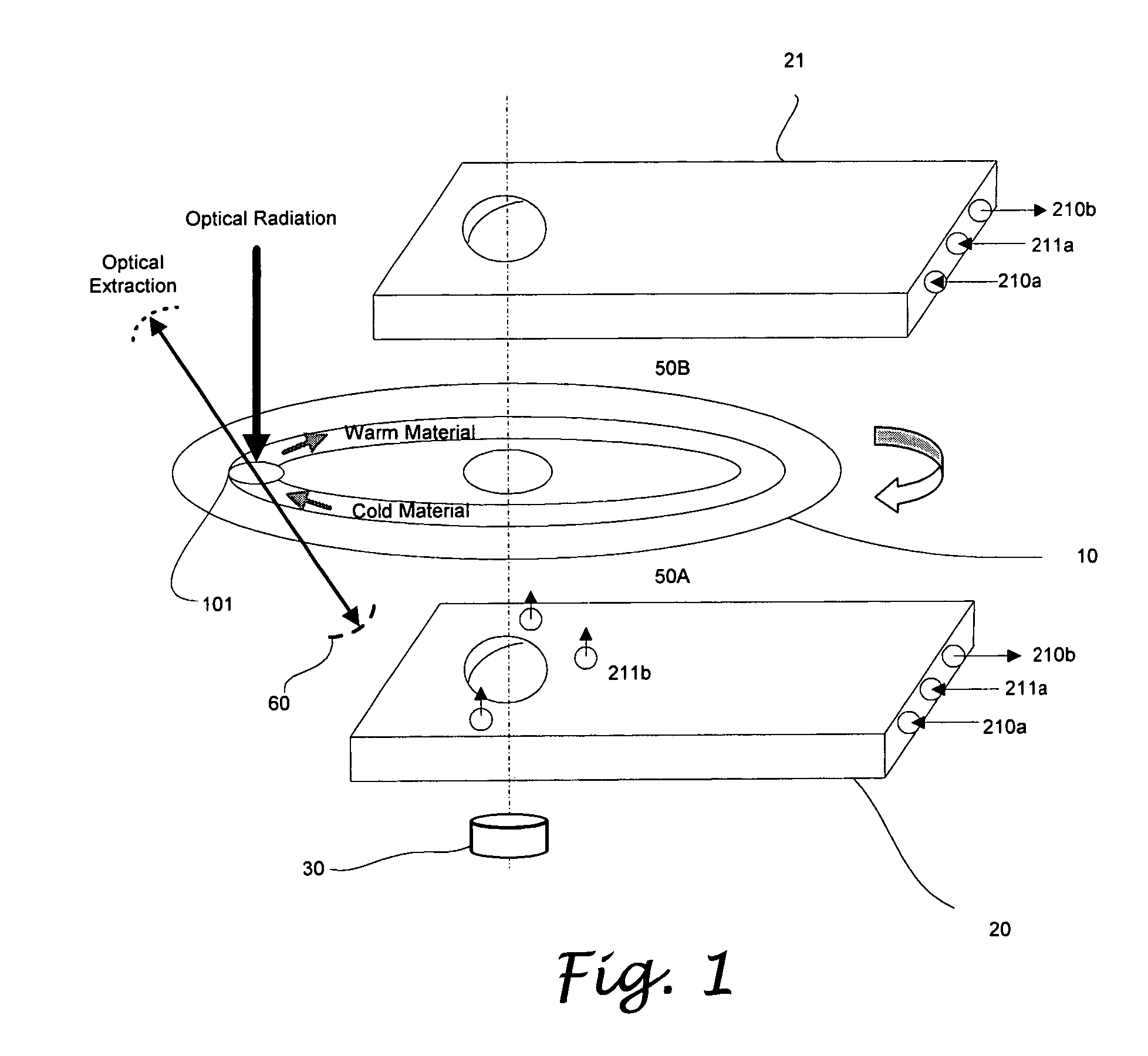
[0023]FIG. 1 illustrates an optical rotary disk module 1 that comprises a rotatable optical disk 10 inserted between a pair of heat sink 20 and 21. As shown, a part of the optical disk 10 is exposed from the heat sinks 20 and 21, such that the optical radiation can be incident thereon and extracted out therefrom. It will be appreciated that, in the current embodim...


PUM


Abstract

A rotary disk module, having a rotary disk is interposed between a pair of heat sinks each spaced from the rotary disk by a gap. A motor is installed for driving the rotary disk to rotate. The gaps are filled with cooling medium such as helium, water or liquid nitrogen to remove the heat generated in the rotary disk by conduction, convection or evaporation. The rotary disk may be fabricated from various materials depending on the intended applications of the module, and the heat sink surfaces are preferably fabricated from materials with higher thermal conductivity. The rotation of the rotary disk allows the regions on which an optical pump radiation is delivered to be separated from the regions from which an optical radiation is extracted. In addition to improved heat dissipation effect, the rotation of the optical disk allows multiple directions of pump energy or multiple sources of pump energies and / or multiple beams of optical radiation to be applied and extracted simultaneously.

Description

CROSS-REFERENCE TO RELATED APPLICATIONS[0001]This application claims priority to Provisional Patent Application Ser. No. 60 / 587,630, filed Jul. 12, 2004, entitled ROTARY DISK LASER MODULE and Provisional Patent Application (Serial No. unknown) Filed Jun. 21, 2005, entitled OPTICAL ROTARY DISK MODULE, the teachings of which are expressly incorporated herein by reference.STATEMENT RE: FEDERALLY SPONSORED RESEARCH / DEVELOPMENT[0002]Not ApplicableBACKGROUND[0003]The present invention relates in general to a method and an apparatus for removing heat generated in a rotary disk by transferring the heat to a heat sink in the proximity thereof.[0004]The waste heat in any solid state laser medium often causes uncorrectable phase aberration in the path of the laser beam due to thermal and stress induced refractive index change. It imposes fundamental limitation on brightness of a conventional continuous-wave or quasi continuous-wave solid state laser in which the gain medium is stationary. Such...

Claims


Application Information

Patent Timeline
Patent Type & Authority Patents(United States)
IPC IPC(8): H01S3/06
CPCF28D15/00F28D19/04G02F1/3501H01S3/025H01S3/0604H01S3/042H01S5/02423H01S3/0608H01S3/1026H01S5/024
Inventor BASU, SANTANU
Owner BASU SANTANU
Why Eureka
Try Eureka