Apparatus and method for reducing EMI generated by a power conversion device

a power conversion device and emi reduction technology, applied in the direction of pulse manipulation, pulse technique, dc circuit to reduce harmonics/ripples, etc., can solve the undesirable side effects of generating electromagnetic interference in the switch power converter, the effect of enhancing emi reduction, and effectively enabling active control and boosting of a common mode capacitan

Active Publication Date: 2009-09-29
WISCONSIN ALUMNI RES FOUND
View PDF10 Cites 11 Cited by
  • Summary
  • Abstract
  • Description
  • Claims
  • Application Information

AI Technical Summary

Benefits of technology

[0012]The present inventors have recognized the need for an improved device for reducing the levels of EMI generated by switching power converters, and have further recognized the limitations associated with conventional filters used for this purpose. The present inventors additionally have recognized that enhanced EMI reduction can be achieved by an improved hybrid filter having both an active filter and a passive filter, where in at least some embodiments the active filter has a voltage controlled voltage source that effectively enables active control over and boosting of a common mode capacitance of the hybrid filter, particularly as a function of frequency, without any concomitant increase in ambient ground leakage currents.
[0014]Additionally, in at least some embodiments, the present invention relates to a filter for use in relation to a power conversion device. The filter includes an active filtering component that operates to provide a variable first capacitance, wherein as a result the filter operates to reduce a level of a common mode current within the power conversion device, whereby an amount of EMI generated by the power conversion device is reduced.
[0015]Further, in at least some embodiments, the present invention relates to a method of operating a power conversion device in a manner resulting in a reduction in an EMI generated by the power conversion device. The method includes providing a hybrid filter that is implemented in combination with the power conversion device, where the hybrid filter includes a passive filter component and an active filter component, the active filter component including a voltage controlled voltage source. The method also includes operating the active filter component so that an overall common mode reactance including a first capacitance of the passive filter component is varied over frequency, and so that a common mode current occurring within the power conversion device is reduced, whereby the EMI generated by the power conversion device is reduced.

Problems solved by technology

Despite their wide use, during operation many switching power converters have the undesirable side-effect of generating electromagnetic interference (EMI).
This side-effect is particularly disadvantageous insofar as, in recent years, the concern over EMI occurring within and between various types of equipment has become heightened, which in turn has lead to the adoption of various regulatory regimes concerning EMI and electromagnetic compatibility of electrical devices.
EMI generated by switching power converters can be particularly significant due to the high frequency switching of electrical quantities (e.g., high frequency changes in voltage and / or current), and due to the short transition intervals involved.
In particular, common mode current paths formed by way of the components of switching power converters and parasitic capacitances existing between the converters and ground often constitute a source of significant capacitive coupling and conducted EMI.
Notwithstanding the limited effectiveness of conventional passive common mode filters in reducing the EMI generated by conventional switching power converters, such filters are likely to be less effective in the future as the switching power converter industry moves toward power converters with higher power densities and performance levels that require higher switching frequencies and reduced transition intervals.
Higher power densities generally result in higher levels of EMI.
Additionally, as the switching frequency of a power converter increases, larger energy levels of noise become present at the low frequency end of the band of interest.
Yet the same is not true for the purpose of increasing the common mode attenuation.
Rather, because the largest capacitance value of the capacitor 5 is bounded by ground leakage current considerations (as well as, in possibly some circumstances, safety considerations), it is not always possible to use an arbitrarily large capacitor.
Further, although a desired level of attenuation could also be obtained by selecting an arbitrarily large inductance value for the inductor 3 (so as to achieve a larger common mode inductance), this is often not possible insofar as large inductors dissipate more heat / power, are physically large, and cannot be easily implemented on integrated circuits.
Although conventional hybrid filters have some limited effectiveness, conventional hybrid filters are unsatisfactory in their performance.
Generating currents that perfectly or substantially cancel out parasitic common mode noise currents is difficult to perform, and becomes even more important as the bandwidth over which those parasitic common mode noise currents occur becomes large.
Complicating matters, the operation of conventional hybrid filters often is not easy to model and consequently is not easy to predict or guarantee.
Thus, conventional hybrid filters not only are unable to fully achieve the goal of canceling out common mode noise currents, but also it is difficult or impossible to determine why this is so and to determine how the filters can be modified to achieve enhanced performance.

Method used


Image

  • Apparatus and method for reducing EMI generated by a power conversion device
  • Apparatus and method for reducing EMI generated by a power conversion device
  • Apparatus and method for reducing EMI generated by a power conversion device

Examples


Embodiment Construction

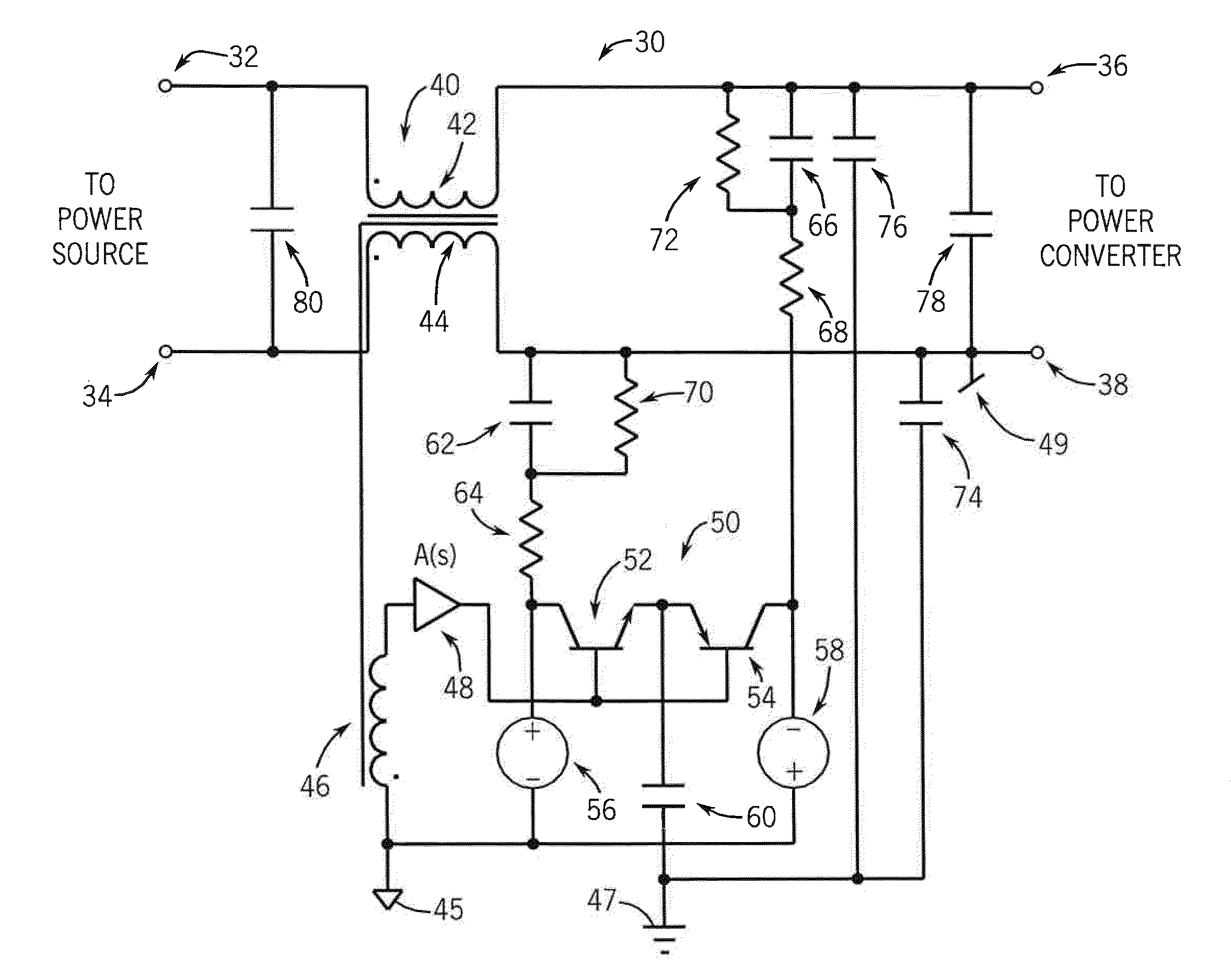
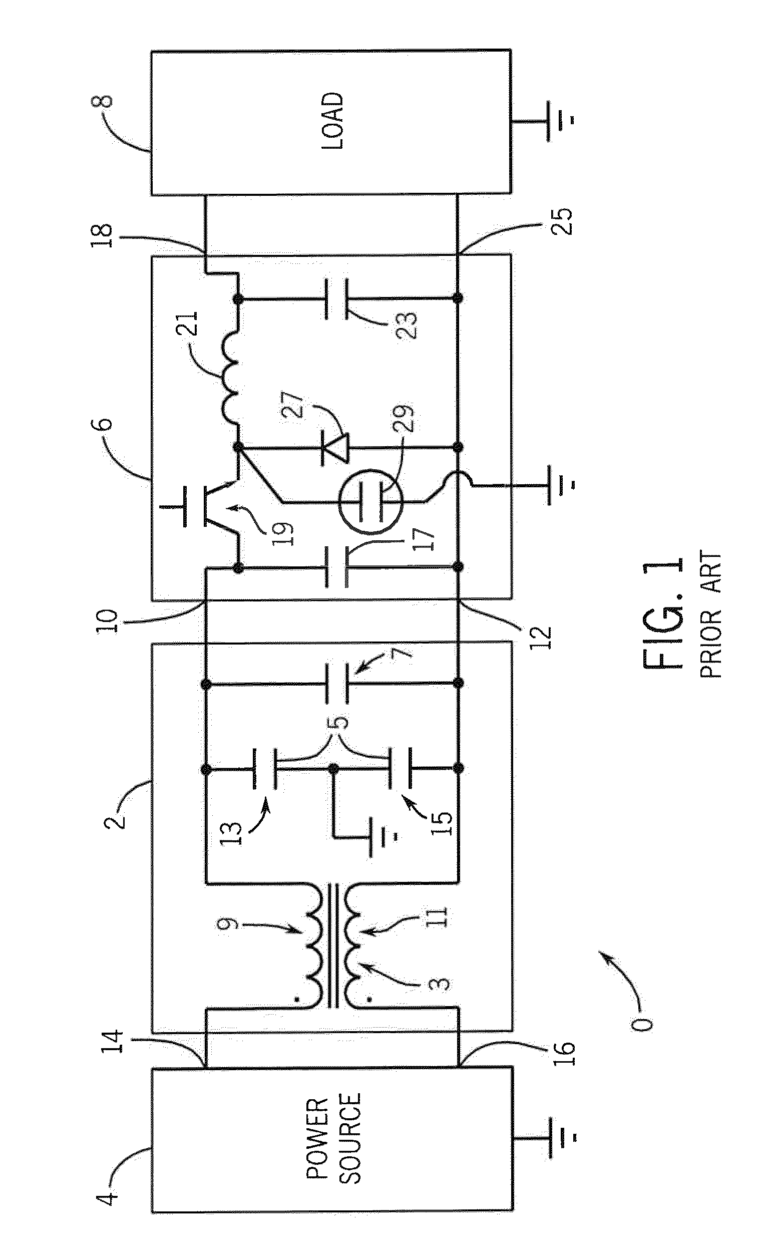
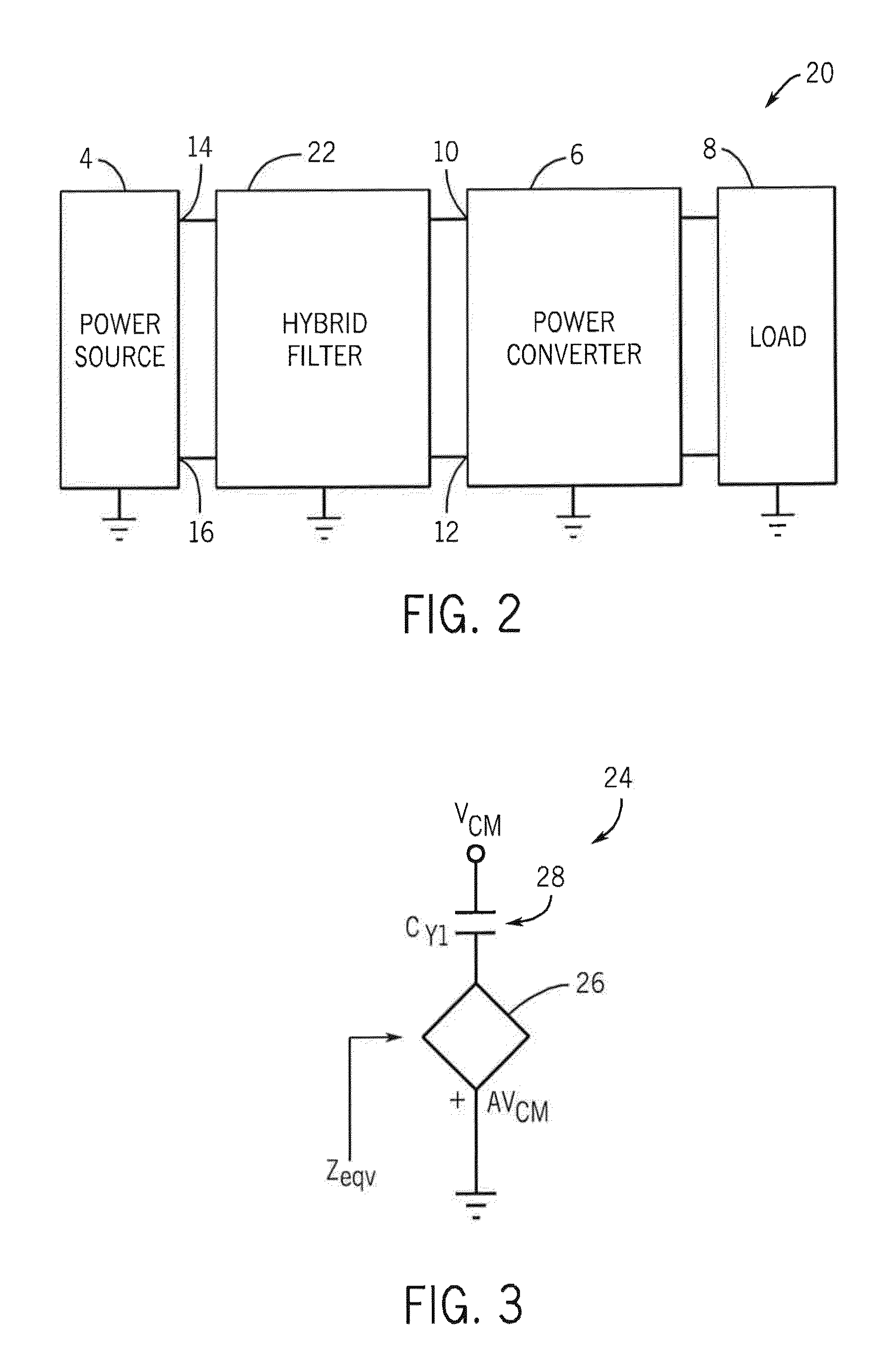
[0022]Referring to FIG. 2, an exemplary improved version of the power system 0 of FIG. 1 is shown as a power system 20. Although the exemplary power system 20 includes the power source 4, the switching power converter 6 and the load 8 of FIG. 1, the power system 20 in place of the filter 2 instead include an improved hybrid filter 22, in accordance with at least some embodiments of the present invention. As described above with respect to the power system 0, the switching power converter 6 includes first and second input terminals 10 and 12, respectively, and the power source 4 includes first and second output terminals 14 and 16, respectively, to which the hybrid filter 22 is coupled. Depending upon the embodiment, the hybrid filter 22 can be embedded within or as part of the switching power converter 6 or alternatively be a device that, while coupled to the power converter, is nevertheless structurally independent of the power converter 6. In at least some embodiments in which the...


PUM


Abstract

An apparatus and method for reducing EMI generated by a power conversion device, as well as a power conversion device employing such apparatus or method (and / or devices employing such a power conversion device) are disclosed. In at least some embodiments, the apparatus includes a hybrid filter for use in reducing EMI. The hybrid filter includes a passive filtering component, and an active filtering component coupled at least indirectly to the passive filtering component. The active filtering component includes a voltage controlled voltage source, and the hybrid filter operates to reduce a level of a common mode current, whereby the EMI generated due to the common mode current is reduced.

Description

CROSS-REFERENCE TO RELATED APPLICATIONS--STATEMENT REGARDING FEDERALLY SPONSORED RESEARCH OR DEVELOPMENT--FIELD OF THE INVENTION[0001]The present invention relates to power conversion devices, and more particularly relates to electrical power conversion devices that employ switching devices to achieve power conversion.BACKGROUND OF THE INVENTION[0002]Switching power converters are useful for converting electrical power having certain characteristics into electrical power having one or more different characteristics. For example, switching power converters can convert a first type of power having a particular voltage or current level or frequency of operation into a second type of power having a different voltage or current level or different frequency of operation. Switching power converters can include, for example, AC to DC converters (e.g., rectifiers), DC to AC converters (e.g., inverters), DC to DC converters (e.g., buck converters, boost converters, and buck-boost converters),...

Claims


Application Information

Patent Timeline
Patent Type & Authority Patents(United States)
IPC IPC(8): H02M1/12H02J1/02H02M1/14
CPCH02M1/44
Inventor MORTENSEN, NICOLAI B.VENKATARAMANAN, VENKATA GIRI
Owner WISCONSIN ALUMNI RES FOUND
Why Eureka
Try Eureka