Self-pinned CPP giant magnetoresistive head with antiferromagnetic film absent from current path

a magnetoresistive head and antiferromagnetic film technology, applied in the direction of instruments, record information storage, substrate/intermediate layer, etc., can solve the problem of increasing noise, unable to obtain sufficient magnetic shield effect, and changing resistance into noise of the output of the head, so as to prevent a sensing current loss, increase the generated joule head, and reduce the effect of nois

Active Publication Date: 2009-10-06
TDK CORPARATION
View PDF35 Cites 23 Cited by
  • Summary
  • Abstract
  • Description
  • Claims
  • Application Information

AI Technical Summary

Benefits of technology

[0021]An antiferromagnetic layer may be provided in the rear of the giant magnetoresistive element in the height direction, for pinning the magnetization direction of the pinned magnetic layer in the height direction. When the antiferromagnetic layer is disposed outside the giant magnetoresistive element, the antiferromagnetic layer does not generate heat to prevent an increase in the generated Joule head even when the sensing current flows through the giant magnetoresistive element. Also, even when the antiferromagnetic layer is provided, the distance between the upper and lower shields need not be increased. By providing the antiferromagnetic layer as described above, magnetization of the pinned magnetic layer can be strongly pinned by an exchange coupling magnetic field produced at the interface between the antiferromagnetic layer and the pinned magnetic layer. In order to prevent a sensing current loss, the antiferromagnetic layer is preferably an insulating antiferromagnetic layer comprising, for example, Ni—O or α-Fe2O3, or comprises an insulating antiferromagnetic comprising, for example, Ni—O or α-Fe2O3 and an antiferromagnetic metal layer interposed between the insulating antiferromagnetic layer and the pinned magnetic layer.
[0022]Furthermore, large-area nonmagnetic metal films are preferably provided between the giant magnetoresistive element and the lower shield layer and between the giant magnetoresistive element and the upper shield layer, respectively, so that the large-area nonmagnetic metal films are in direct con

Problems solved by technology

The change in resistance becomes noise of the output of the head.
Particularly, with a high current density, there is the problem of increasing the noise due to the AMR effect.
However, a sufficient magnetic shield effect cannot be obtained by using the shield material with a low AMR effect.
Since the temperature of the whole of the he

Method used


Image

  • Self-pinned CPP giant magnetoresistive head with antiferromagnetic film absent from current path
  • Self-pinned CPP giant magnetoresistive head with antiferromagnetic film absent from current path
  • Self-pinned CPP giant magnetoresistive head with antiferromagnetic film absent from current path

Examples


first embodiment

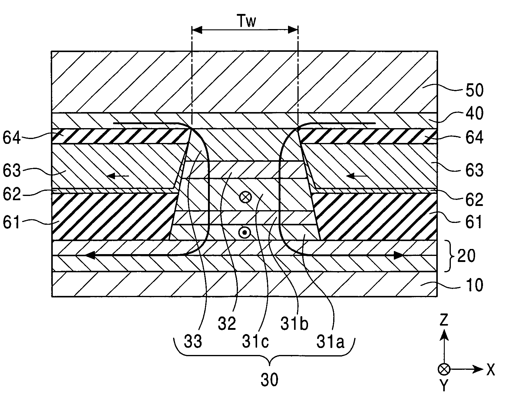
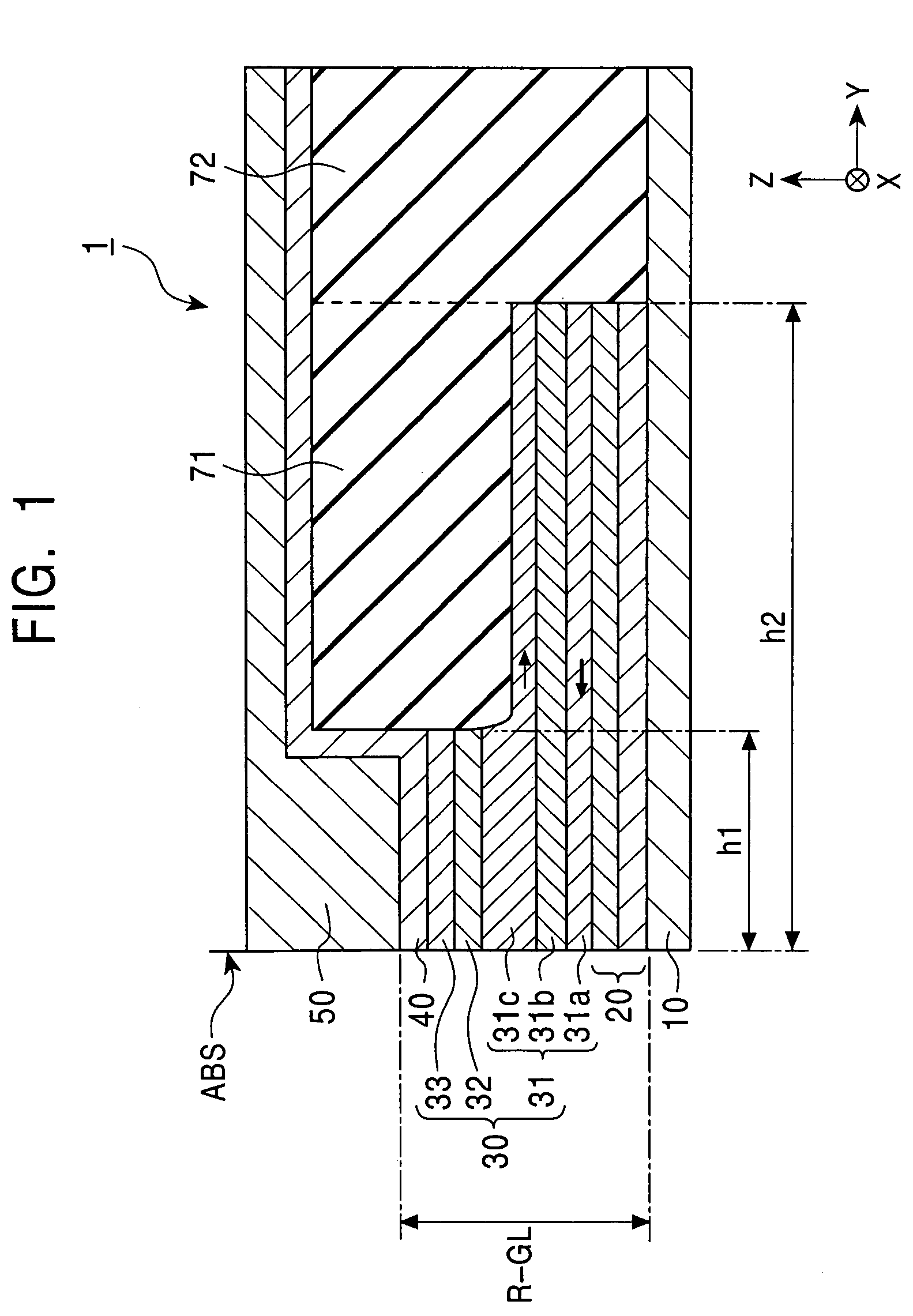
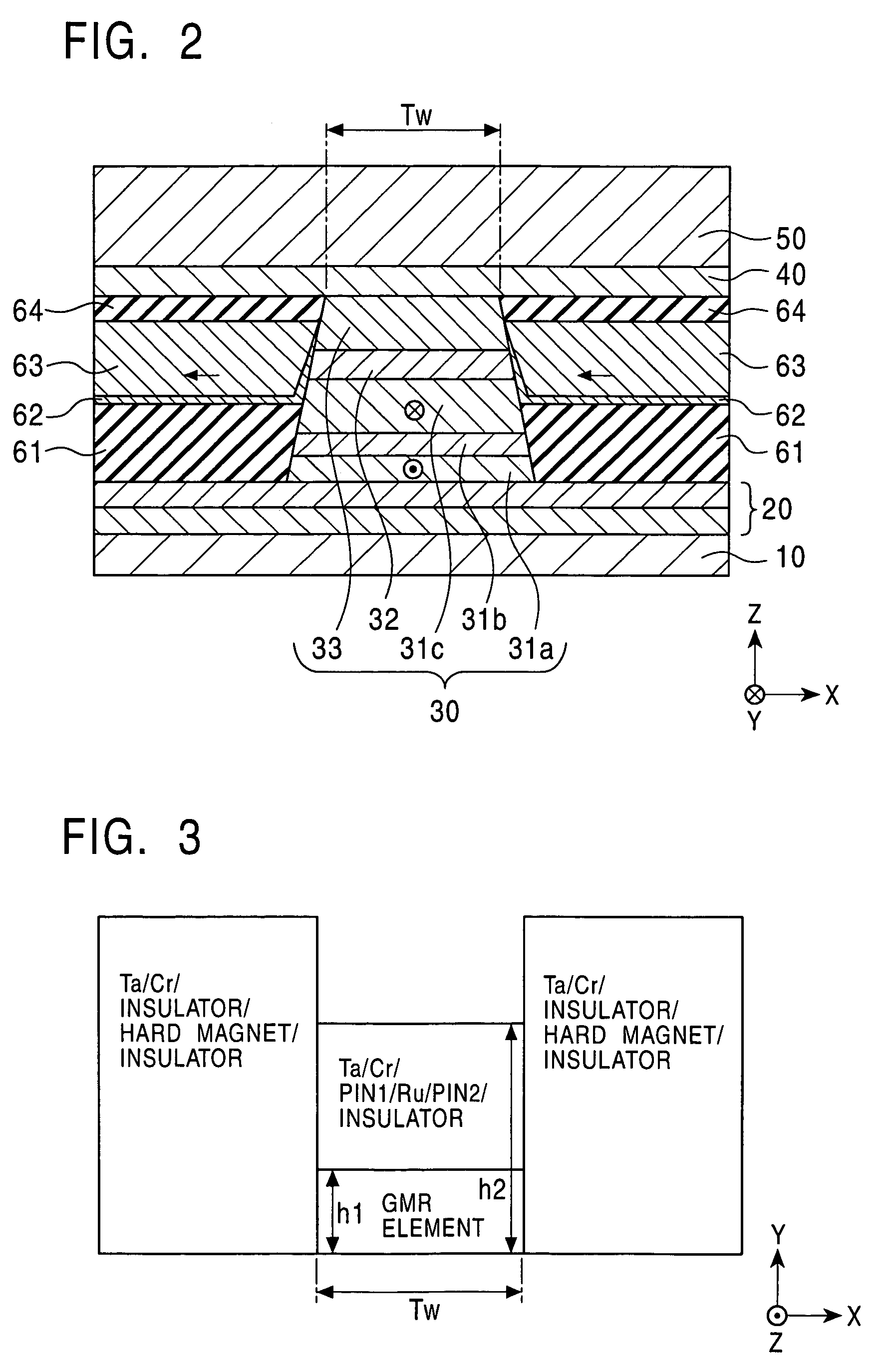
[0047]FIGS. 1 to 8 show a CPP giant magnetoresistive head (CPP-GMR head) according to the present invention. FIG. 1 is a partial sectional view showing the structure of a CPP GMR head 1, taken along a central line of an element, FIG. 2 is a partial sectional view showing the structure of the CPP GMR head 1, as viewed from a surface facing a recording medium, and FIG. 3 is a schematic top plan view of a GMR element 30.

[0048]The CPP-GMR head 1 comprises lower and upper shield layers 10 and 50 with a predetermined shield distance R-GL therebetween in the Z direction shown in the drawing, a lower large-area nonmagnetic metal film 20, the GMR element 30 exhibiting a giant magnetoresistive effect, and an upper large-area nonmagnetic metal film 40, the lower and upper large-area nonmagnetic metal films 20 and 40 and the GMR element 30 being disposed between the lower and upper shield layers 10 and 50.

[0049]Each of the lower and upper shield layers 10 and 50 functions as a magnetic shield a...

second embodiment

[0080]FIGS. 9 to 13 show a CPP giant magnetoresistive head (CPP-GMR head) according to the present invention. The second embodiment is different from the first embodiment in that an antiferromagnetic layer is provided in the rear of a GMR element in the height direction, for pinning the magnetization direction of a pinned magnetic layer in the height direction.

[0081]FIG. 9 is a partial sectional view showing the structure of a CPP GMR head 201, taken along a central line of an element, FIG. 10 is a partial sectional view showing the structure of the CPP GMR head 201, as viewed from a surface facing a recording medium, and FIG. 11 is a schematic top plan view of a GMR element 30. In FIGS. 9 to 11, the functions, shapes, materials and thicknesses of layers denoted by the same reference numerals as those in the first embodiment shown in FIGS. 1 to 3 are the same as those in the first embodiment, and thus the description thereof is omitted.

[0082]The CPP-GMR head 201 comprises an antifer...


PUM


Abstract

A CPP giant magnetoresistive head includes lower and upper shield layers, and a giant magnetoresistive element disposed between the upper and lower shield layers and including a pinned magnetic layer, a free magnetic layer and a nonmagnetic layer disposed between the pinned magnetic layer and the free magnetic layer. In the CPP giant magnetoresistive head, the pinned magnetic layer extends to the rear of the nonmagnetic layer and the free magnetic layer in the height direction, and the dimension of the pinned magnetic layer in the height direction is larger than that in the track width direction. Also, the pinned magnetic layer comprises a magnetic material having a positive magnetostriction constant or a magnetic material having high coercive force, and the end of the pinned magnetic layer is exposed at a surface facing a recording medium.

Description

[0001]This application claims the benefit of priority to Japanese Patent Application No. 2003-114189, 2003-195159 and 2004-047757 herein incorporated by reference.BACKGROUND OF THE INVENTION[0002]1. Field of the Invention[0003]The present invention relates to a CPP (Current Perpendicular to the Plane) giant magnetoresistive head in which a sensing current flows in the thickness direction (perpendicularly to the film plane).[0004]2. Description of the Related Art[0005]Giant magnetoresistive (GMR) elements used for hard disk devices and magnetic sensors are roughly divided into a CIP (Current in the Plane) type in which a sensing current flows in parallel with the film plane of each of layers constituting an element, and a CPP (Current Perpendicular to the Plane) type in which a sensing current flows perpendicularly to the film plane of each of the layers constituting an element.[0006]FIG. 21 is a longitudinal sectional view showing the structure of a CPP-GMR head using a conventional...

Claims


Application Information

Patent Timeline
IPC IPC(8): G11B5/39G11B5/127G11B5/33H01F10/16H01F10/32H01L43/08H01L43/10
CPCG11B5/3903G11B5/398G11B5/3163
Inventor SAITO, MASAMICHINISHIYAMA, YOSHIHIROIDE, YOSUKEUMETSU, EIJIHASEGAWA, NAOYAHAYAKAWA, YASUO
Owner TDK CORPARATION
Why Eureka
Try Eureka