Power output apparatus, vehicle equipped with power output apparatus, and control method of power output apparatus

a technology of power output apparatus and control method, which is applied in the direction of engine-driven generators, machines/engines, process and machine control, etc., can solve the problem of insufficient chance of detecting the current status of oxygen concentration sensors

Active Publication Date: 2009-10-06
TOYOTA JIDOSHA KK
View PDF12 Cites 37 Cited by
  • Summary
  • Abstract
  • Description
  • Claims
  • Application Information

AI Technical Summary

Benefits of technology

[0006]The power output apparatus of the invention, the vehicle equipped with the power output apparatus, and the control method of the power output apparatus thus aim to assure the sufficient chance of detecting the current status of an oxygen concentration measurement unit. The power output apparatus of the invention, the vehicle equipped with the power output apparatus, and the control method of the power output apparatus also aim to ensure a sufficient response to a driver's drive demand during detection of the current status of the oxygen concentration measurement unit.
[0020]In the control method of the power output apparatus of the invention, the step (a) may detect a failure of the oxygen concentration measurement unit as the current status, based on a result of determination whether the oxygen concentration measured by the oxygen concentration measurement unit has continuously been out of a specified normal range for a preset time period. This arrangement enables accurate detection of a failure of the oxygen concentration measurement unit.

Problems solved by technology

There is accordingly only the insufficient chance of detecting the current status of the oxygen concentration sensor.

Method used


Image

  • Power output apparatus, vehicle equipped with power output apparatus, and control method of power output apparatus
  • Power output apparatus, vehicle equipped with power output apparatus, and control method of power output apparatus
  • Power output apparatus, vehicle equipped with power output apparatus, and control method of power output apparatus

Examples


Embodiment Construction

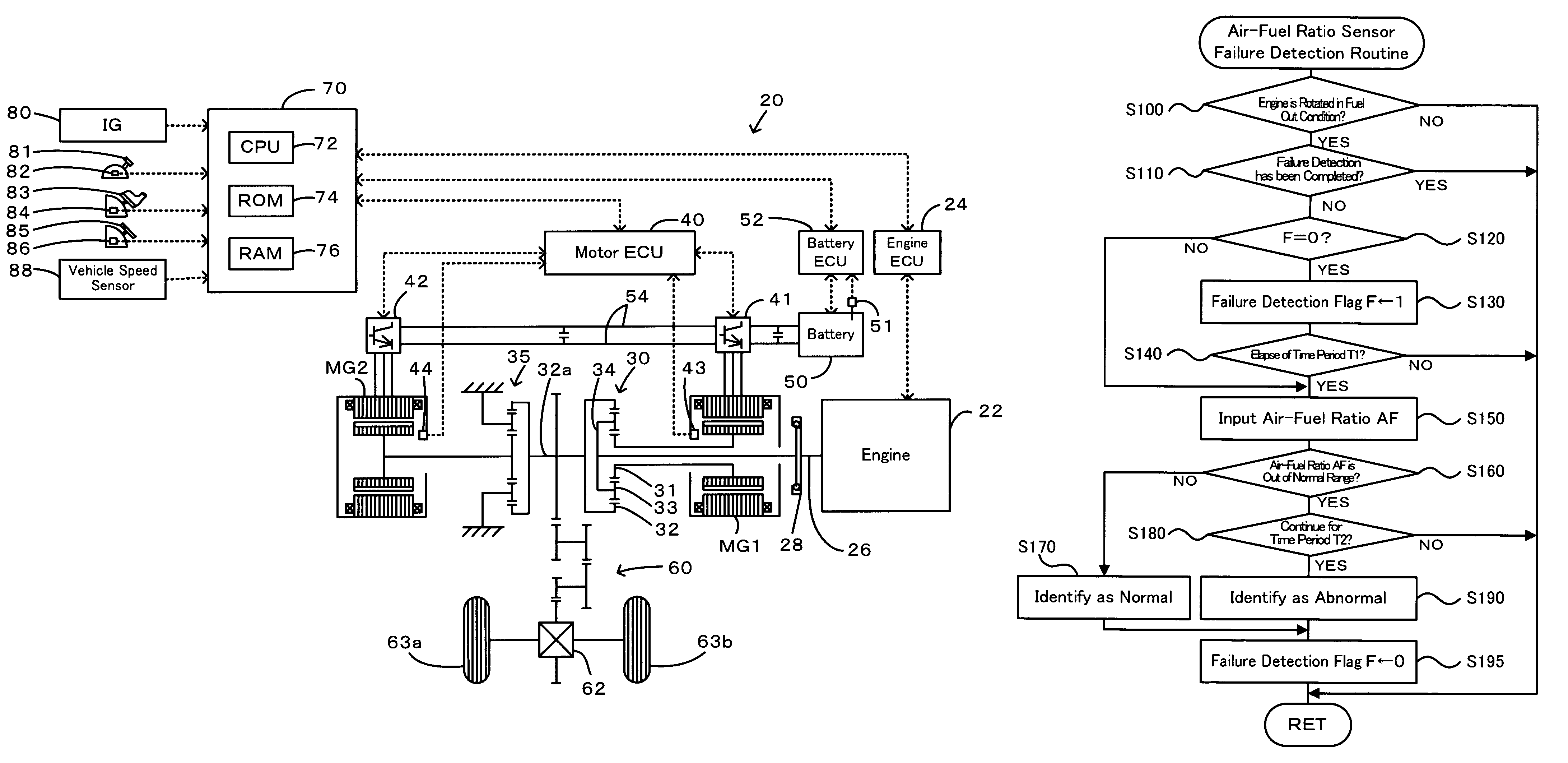
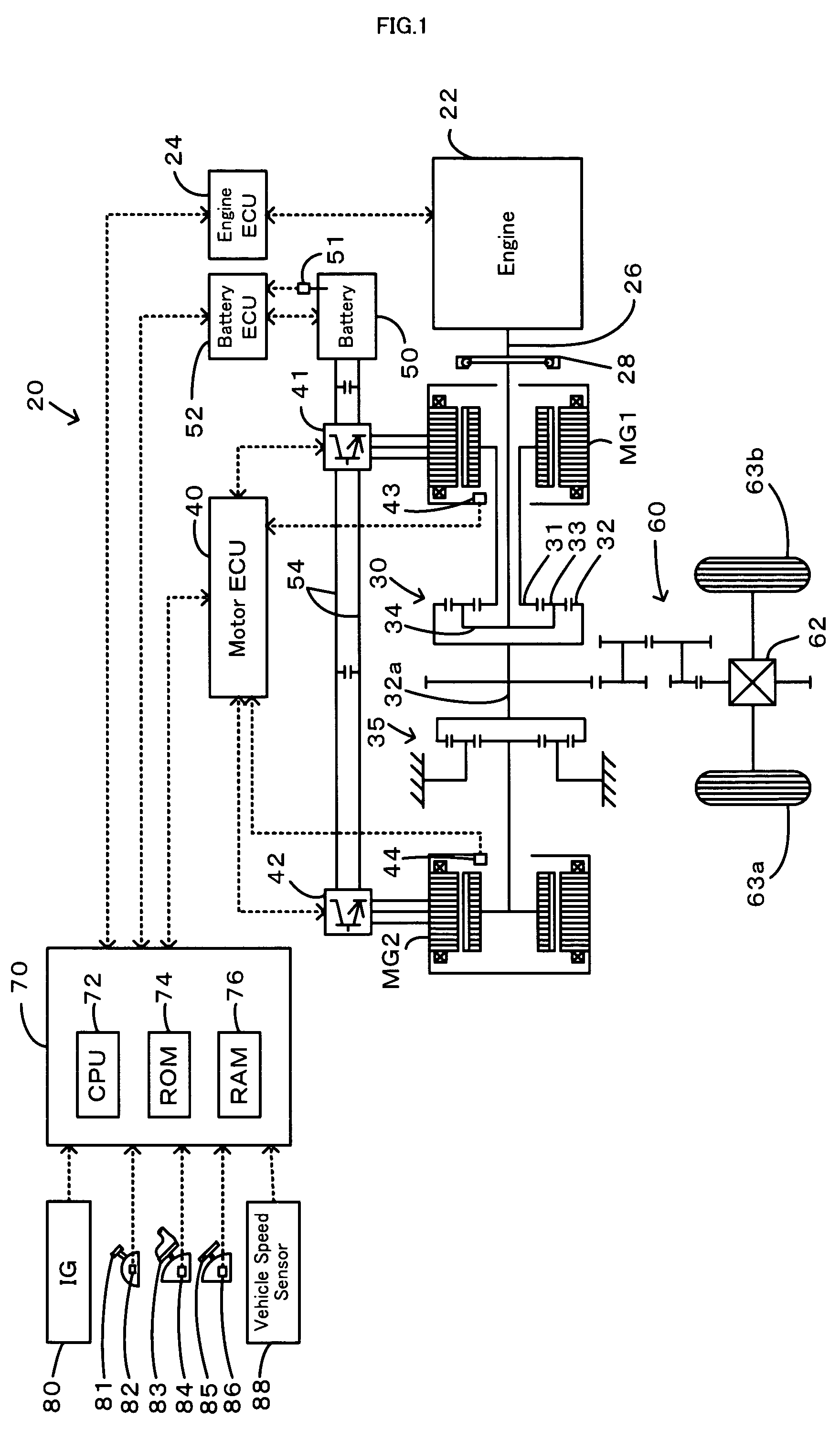
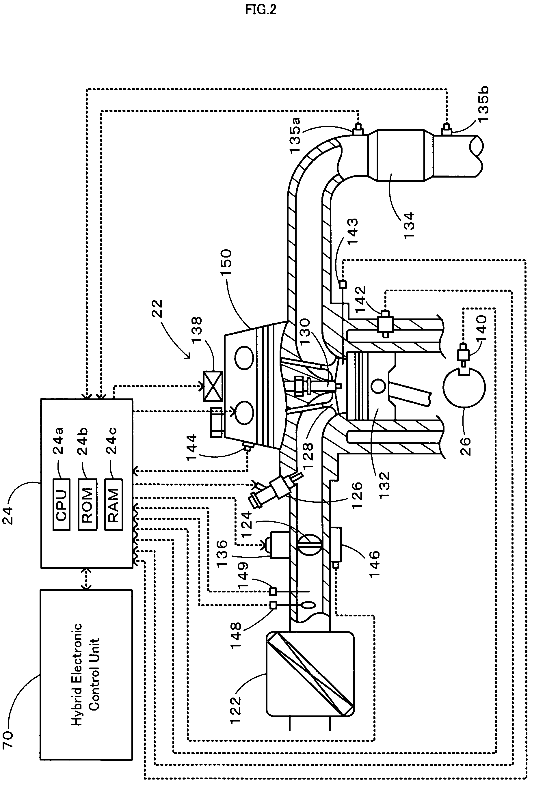
[0033]One mode of carrying out the invention is discussed below as a preferred embodiment. FIG. 1 schematically illustrates the construction of a hybrid vehicle 20 with a power output apparatus mounted thereon in one embodiment of the invention, and FIG. 2 schematically illustrates the structure of an engine mounted on the hybrid vehicle of the embodiment. As illustrated, the hybrid vehicle 20 of the embodiment includes an engine 22, a three shaft-type power distribution integration mechanism 30 that is linked with a crankshaft 26 functioning as an output shaft of the engine 22 via a damper 28, a motor MG1 that is linked with the power distribution integration mechanism 30 and is capable of generating electric power, a reduction gear 35 that is attached to a ring gear shaft 32a functioning as a drive shaft connected with the power distribution integration mechanism 30, another motor MG2 that is linked with the reduction gear 35, and a hybrid electronic control unit 70 that controls ...


PUM


Abstract

A vehicle is equipped with a planetary gear mechanism including a sun gear, a carrier, and a ring gear that are respectively connected to a first motor, an engine, and a driveshaft. A second motor is further linked to the driveshaft. An air-fuel ratio sensor located in an exhaust system of the engine detects the air-fuel ratio while the engine is rotated in a fuel cut state. Normality or abnormality of the air-fuel ratio sensor is identified, based on a result of determination whether the detected air-fuel ratio is out of a specified normal range. When engine stop conditions for stopping the operation (rotation) of the engine are satisfied during execution of failure detection of the air-fuel ratio sensor (steps S300 and S310), the drive control of the invention maintains the rotation of the engine in the fuel cut state until completion of the failure detection of the air-fuel ratio sensor and controls the first motor to motor the engine (step S330). The operation of the engine is stopped on completion of the failure detection (step S320).

Description

BACKGROUND OF THE INVENTION[0001]1. Technical Field[0002]The present invention relates to a power output apparatus that outputs power to a driveshaft, a vehicle equipped with the power output apparatus, and a control method of the power output apparatus.[0003]2. Description of the Related Art[0004]One proposed configuration of a power output apparatus uses an oxygen concentration sensor that is located in an exhaust conduit of an engine to measure the oxygen concentration in exhaust emission from the engine (see, for example, Japanese Patent Laid-Open Gazette No. H10-212999). The proposed power output apparatus increases the power supply to a heater of the oxygen concentration sensor and raises the voltage applied to a sensor element in response to a fuel cut operation of the engine during deceleration. An output signal of the oxygen concentration sensor under the condition that an integrated value of exhaust flow rate since the start of the fuel cut condition reaches or exceeds a p...

Claims


Application Information

Patent Timeline
Patent Type & Authority Patents(United States)
IPC IPC(8): G06F19/00B60K1/02F02D41/14G01M15/00B60K6/24B60K6/44B60K6/445B60K6/448B60K6/52B60L50/16B60W10/06B60W10/08B60W20/00F02D29/02F02D41/22F02D45/00
CPCB60K6/445B60W10/06B60W10/08B60W20/00F02D41/1495F02D41/222F02D41/123B60W2710/0616Y10T477/23Y02T10/6239Y02T10/6286Y02T10/62F02D45/00F02D29/00F02D35/00B60W20/50B60W2510/0619
Inventor UTSUMI, ATSUKONISHIGAKI, TAKAHIRO
Owner TOYOTA JIDOSHA KK
Why Eureka
Try Eureka