
Versatile lighting device

a lighting device and aversive technology, applied in the field ofversatile lighting devices, can solve the problems of relatively short charge time and relatively long run-time of batteries

Inactive Publication Date: 2009-10-20
VERSALITE ASSOCS
View PDF23 Cites 46 Cited by
  • Summary
  • Abstract
  • Description
  • Claims
  • Application Information

AI Technical Summary

Benefits of technology

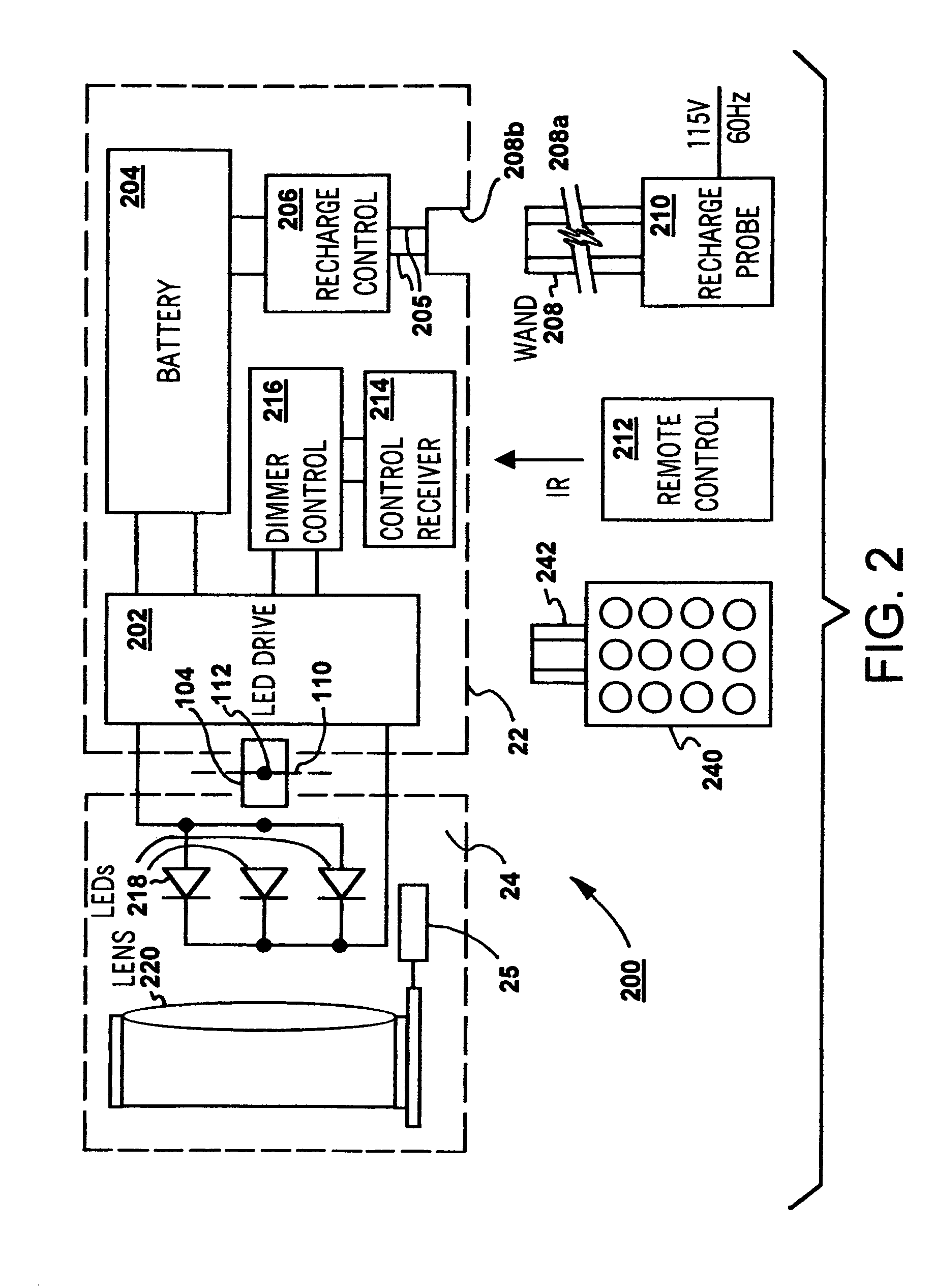
[0009]According to one embodiment of the invention, a versatile lighting device is provided which is operable to produce appealing and pleasing illumination. The lighting device may not require any connection to an electric grid power source or outlet. One or more batteries that power the lighting device may be charged without removal from the installed lighting device. The batteries may have relatively long run-time and short charge time. Alternatively, the lighting device may be powered by a low-profile power unit which is wired to an AC power source. The lighting device may comprise a low-power consuming light source, such as one or more light emitting diodes (LEDs), to provide bright and warm illumination that is comparable to natural light. The lighting device may be provided in various configurations, including wall sconces, picture lights and various forms of decorative lighting, and may be remotely controlled to achieve desired lighting effects, including position, intensity and focus.
[0010]The present invention still further provides a versatile lighting device which may be mounted in a wide variety of locations, and powered by an onboard battery power source. The battery source may be conveniently recharged without removal from the lighting device by charging apparatus which includes an elongated wand, rod or pole for connecting a source of recharging power to the battery. The battery charging apparatus may be easily connected to the lighting device and easily removed therefrom. The charging apparatus may be stored in a closet or other storage space when not needed and may include a telescoping type rod or pole to facilitate access between a source of charging power and the lighting device itself.

Problems solved by technology

The batteries may have relatively long run-time and short charge time.

Method used


Image

  • Versatile lighting device
  • Versatile lighting device
  • Versatile lighting device

Examples


Embodiment Construction

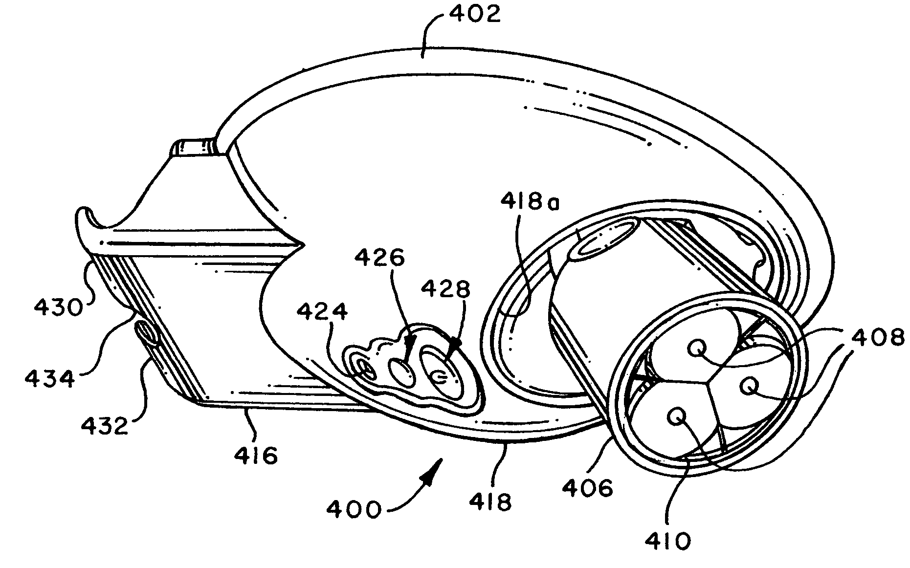
[0031]Reference will now be made in detail to the embodiments of the invention which are illustrated in the accompanying drawings. The drawings are not necessarily to scale and certain components may be shown in schematic form in the interest of clarity and conciseness.

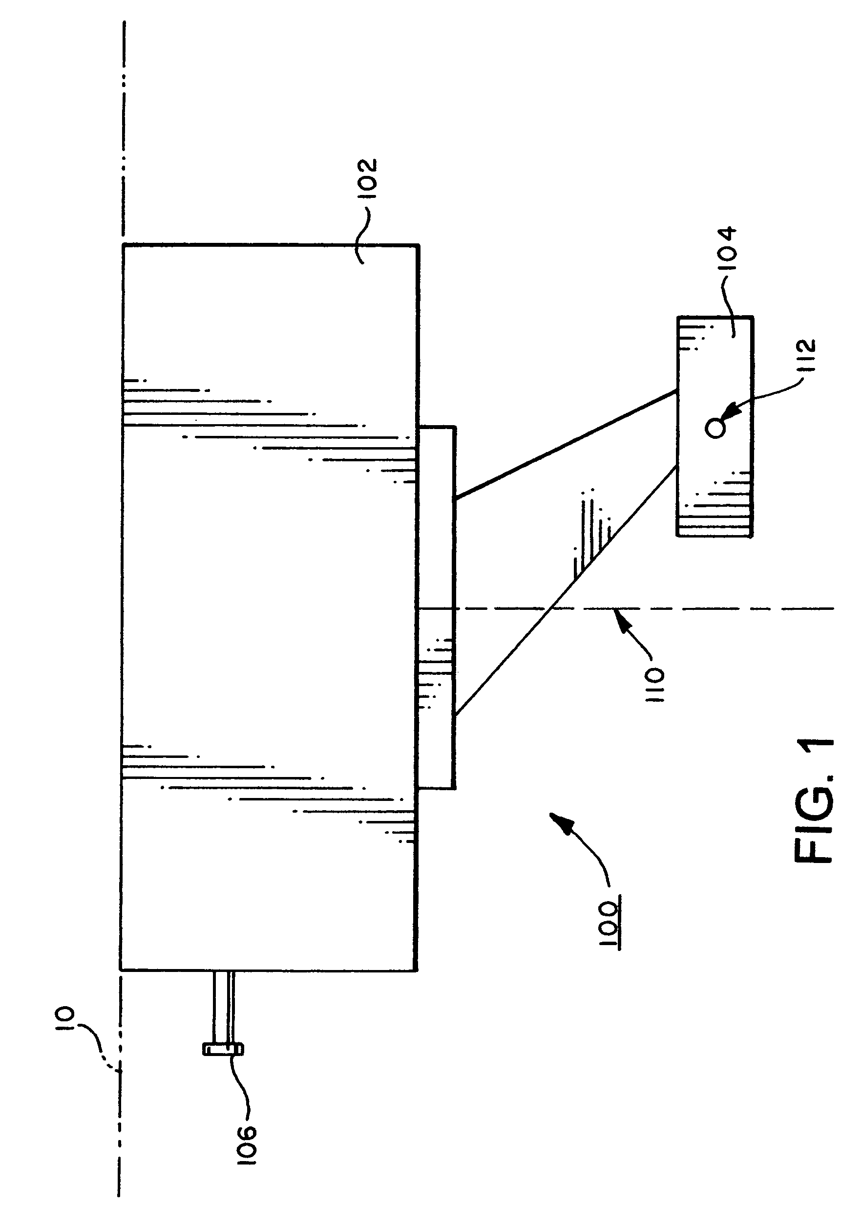
[0032]Referring to FIG. 1, there is shown an exemplary lighting device 100 according to one embodiment of the invention. The lighting device 100 may comprise two main components: a base 102 and a pan-tilt assembly 104. The base 102 may house electronics and one or more batteries. The pan-tilt assembly 104 may house a lens, one or more LEDs, and a heat sink.

[0033]The base 102 may be mounted to a surface 10 or a recess opening therein. The base 102 may be mounted via a number of mechanisms. For example, the base 102 may be screw-mounted via a ceiling mount or a wall mount, or the base 102 may include a hook and loop patch-type fastening means, an adhesive pad or other detachable mounting devices. Since the lighting devi...


PUM


Abstract

A wall or ceiling mountable lighting device comprises a self-contained single or multiple LED light source for emitting warm yellow-white light corresponding to halogen or incandescent light and a control circuit controlled by a remote control unit to energize and deenergize the light source and control light intensity. A rechargeable battery power source mounted on the lighting device is connectable to apparatus for charging the battery without removing the battery from the device. The apparatus includes an elongated probe assembly releasably connectable to the lighting device to perform the recharging process. The lighting device is particularly adapted for ease of placement of a light source for decorative purposes and / or illuminating artifacts in locations which would require substantial structural modifications to install conventional lighting.

Description

CROSS REFERENCE TO RELATED APPLICATION[0001]This application claims the benefit of prior provisional application Ser. No. 60 / 650,536, filed Feb. 8, 2005.BACKGROUND OF THE INVENTION[0002]The present invention relates to lighting devices, particularly to a versatile lighting device, and more particularly to a versatile lighting device for art gallery, display and decorative lighting applications.[0003]Picture lights and display lights have been widely used in public establishments (e.g., galleries and museums) to illuminate paintings, artifacts and architectural details for enhanced visual effects. Recently, these lighting devices are slowly making their way into private homes. Many people attempt to make their homes appear warmer and more attractive by installing what used to be considered professional lighting fixtures. Private individuals may also have the need to showcase a wide range of possessions, such as paintings, prints, photographs, awards, artifacts, plants, flowers, and a...

Claims


Application Information

Patent Timeline
Patent Type & Authority Patents(United States)
IPC IPC(8): F21L4/00
CPCF21S9/02F21V14/06F21V21/15F21V23/0435F21Y2101/02F21W2131/304F21W2131/308F21Y2115/10
Inventor DOWDY, RANDAL A.GUYER, JEFFREY A.PENDLETON, JUSTIN D.RODERMAN, BRIAN L.TANNER, ERIC A.
Owner VERSALITE ASSOCS
Learn More