
Eureka
For R&D, Eureka makes reading and utilizing patents & technical documents easy.
Eureka AIR
Designed for self-driven R&D workflows. Generate viable solutions, solve complex R&D challenges, empower your innovation with AI.

Eureka Materials
Designed for material experts only. Revolutionize your material R&D, from search, analyze, to developing new materials.

TechResearch
Generate reliable direction feasibility study reports for your R&D in just a few steps.

TechSeek
Discover and master advanced knowledge NOW. Basics, ideas, possibilities, all at once.

TechMind
As an expert in R&D Theories, TechMind can generates customized viable solutions instantly.

TechRisk
Analyze your overall solution with one click, know your potential R&D risks in advance.

TechMonitor
Get weekly tech updates, stay abreast of the latest tech innovations and key insights.
Transmission apparatus for making ring switching at SONET/SDH and RPR levels
- Summary
- Abstract
- Description
- Claims
- Application Information
AI Technical Summary
Benefits of technology
Problems solved by technology
Method used
Image

Examples
first embodiment
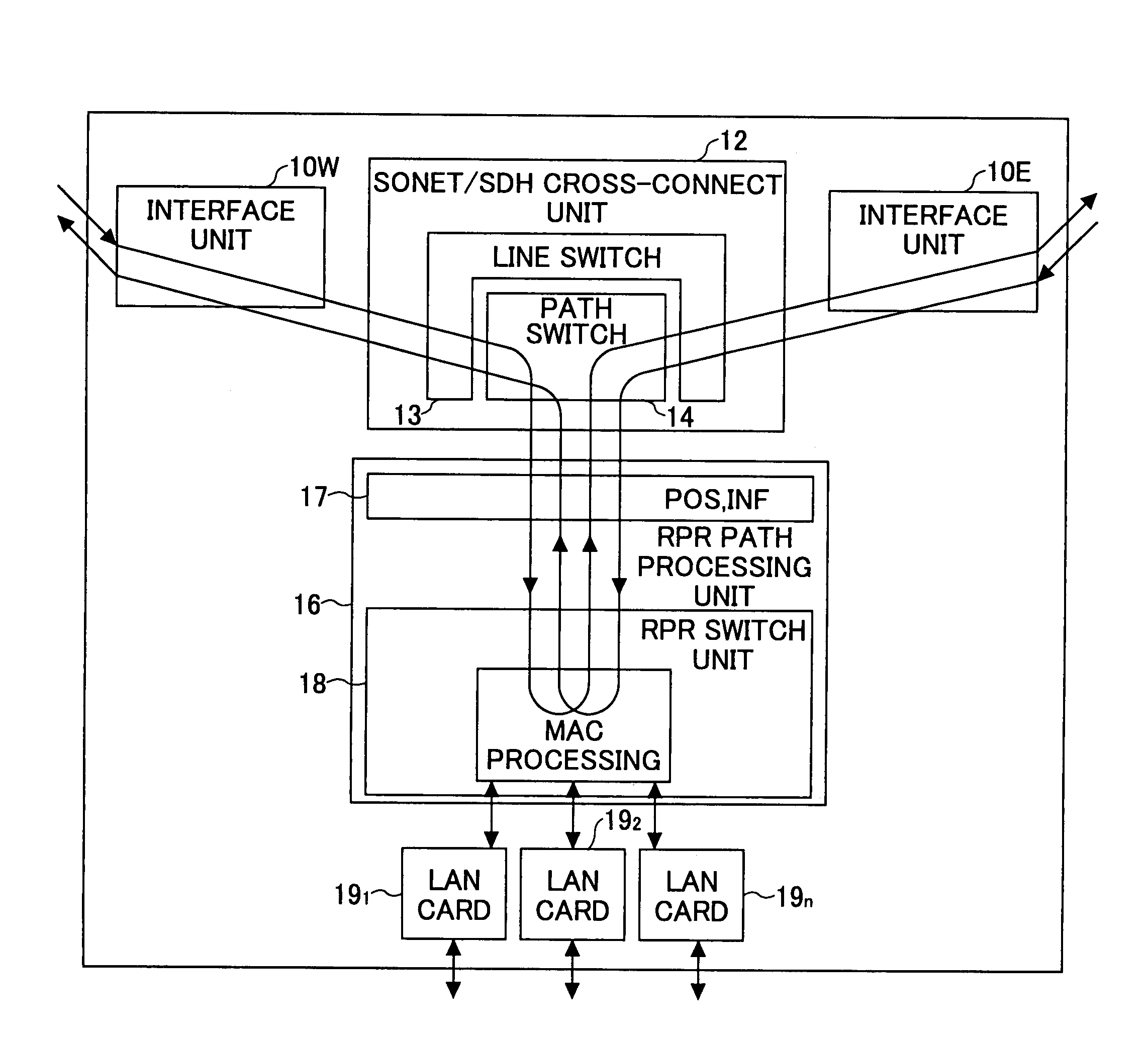
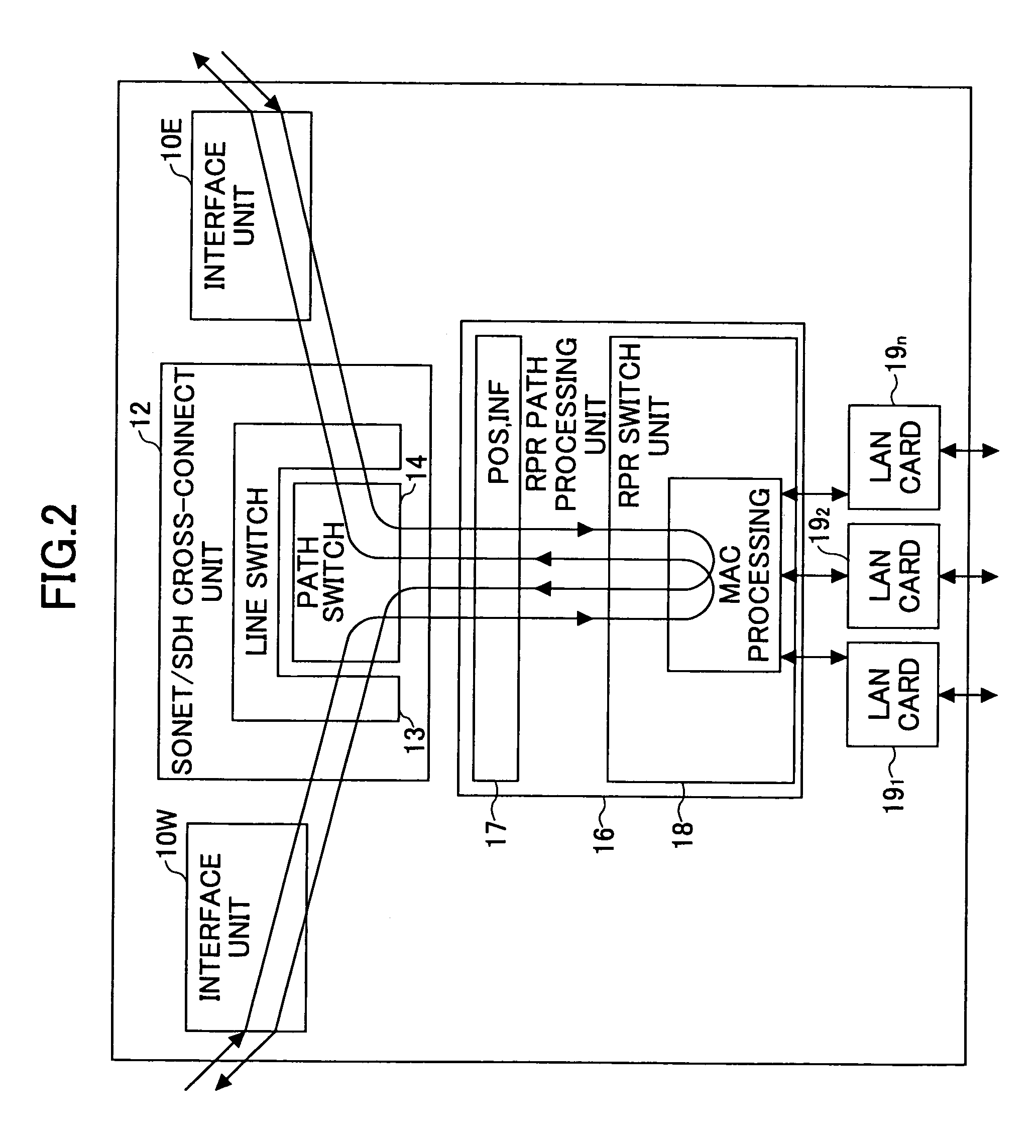
[0041]FIG. 2 is a block diagram showing the hybrid transmission apparatus of the invention. In FIG. 2, interface units 10W and 10E convert optical signals of SONET / SDH such as 40 Gbps, 10 Gbps, 2.5 Gbps, or 622 Mbps (OC768, OC192, OC48, or OC12) signals into the electrical signals, and synchronize the signals with a reference clock that is internal to the apparatus. The interface units 10W and 10E then establish inter-block interface with an SONET / SDH cross-connect unit 12 by use of signals having the STS-48 (STM16) / STS-12 (STM4) format.
[0042]FIG. 3A is an illustrative drawing showing the structure of an SOH (section overhead) complying with STS-12. FIG. 3B is a table showing the contents of bytes A1-H3 of the SOH. FIG. 3C is a table showing the contents of each bit of the E1 byte, which is concatenation information.
[0043]Connection between the SONET / SDH cross-connect unit 12 and the interface units 10W and 10E is made by placing the SONET / SDH cross-connect unit 12 at a center with ...
second embodiment
[0054]FIG. 5 is a block diagram showing the hybrid transmission apparatus of the invention. In particular, a drop side where low-speed signals are extracted from a high-speed ring is illustrated in detail. Signals supplied from an NE (network element) that is situated upstream as a signal source may suffer path failure that may be the disconnection of signals or simply the degradation of signal quality. In FIG. 5, thick solid arrows indicate detection points and processing points along the signal flow so as to illustrate how to achieve effective path protection in an NE that is situated downstream as a signal receiver.
[0055]Moreover, a mechanism is also illustrated with regard to how to promptly inform NEs situated downstream when a serious failure such as disconnection or the loss of signal synchronization occurs upstream. Further illustrated is a mechanism regarding how the NE having received or detected a failure promptly informs the signal source and circumvents the failure auto...
PUM
 Abstract
Description
Claims
Application Information
 - R&D Engineer
- R&D Manager
- IP Professional
- Industry Leading Data Capabilities
- Powerful AI technology
- Patent DNA Extraction
Browse by: Latest US Patents, China's latest patents, Technical Efficacy Thesaurus, Application Domain, Technology Topic, Popular Technical Reports.
© 2024 PatSnap. All rights reserved.Legal|Privacy policy|Modern Slavery Act Transparency Statement|Sitemap|About US| Contact US: help@patsnap.com