Solar absorber

a solar absorber and solar energy technology, applied in solar ray transmission, solar energy devices, furniture, etc., can solve the problems of thermal loss and absorber failure, and achieve the effect of increasing the yield of captured heat and reducing reradiation loss

Inactive Publication Date: 2009-10-27
SCHOTT AG
View PDF56 Cites 4 Cited by
  • Summary
  • Abstract
  • Description
  • Claims
  • Application Information

AI Technical Summary

Benefits of technology

[0010]The object of the invention is to minimize reradiation losses in as much of a concentrating solar absorber as possible, namely both on the...

Problems solved by technology

In addition to optical losses, thermal losses also occur in the absorber since it assumes a higher temperature than the environment due to the conversion of the solar radiation into heat.
The techn...

Method used


Image

  • Solar absorber
  • Solar absorber
  • Solar absorber

Examples


Embodiment Construction

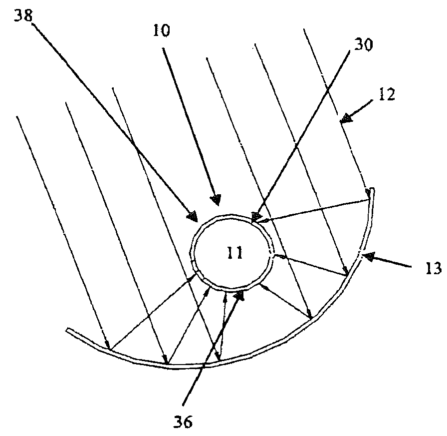
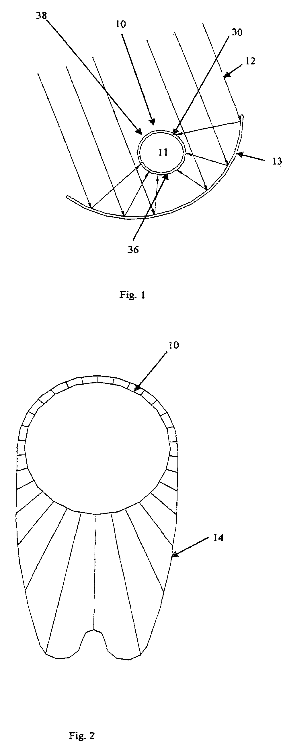
[0050]FIG. 1 shows the absorber body 10, which in this instance is an elongated absorber tube 30 through the interior 11 of which a heat transfer medium flows. A concentrator 13 in the form of a parabolic mirror concentrates and focuses the incident solar radiation 12 onto the absorber body 10. The absorber body 10 absorbs the solar radiation and converts it into heat, which is transmitted to the heat transfer medium. This heats the heat transfer medium.

[0051]FIG. 2 shows the distribution of radiant energy density 14 over the circumference of the absorber body in polar coordinates. On the side 36 oriented toward the concentrator 13, the radiant energy density is high. On the side 38 oriented away from the concentrator, the radiant energy density is equal to the radiant energy density of the incident solar radiation, which could be expressed as the value “1”.

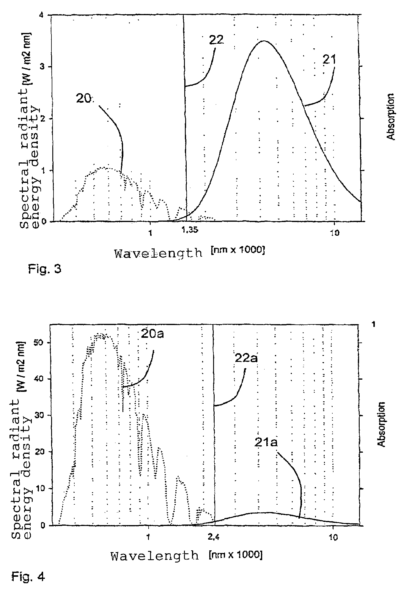
[0052]FIG. 3 shows the spectral distribution of the radiant energy density of the incident solar radiation by means of the curv...


PUM

PropertyMeasurementUnit
Fractionaaaaaaaaaa
Fractionaaaaaaaaaa
Thicknessaaaaaaaaaa

Abstract

The solar absorber is equipped with an absorber body (10) that absorbs incident solar energy (12) and converts it to heat. The absorber body has a selective absorption layer (17) on a side (36) oriented toward the concentrator (13) and another selective absorption layer (18) on an opposite side (38) oriented away from the concentrator (13). The selective absorption layers (17, 18) have threshold wavelengths below which solar radiation is absorbed and above which a reradiation capacity of the absorber body is suppressed. The threshold wavelength of the selective absorption layer (17) on the side (36) of the absorber body that is oriented toward the concentrator is greater than the other threshold wavelength of the other selective absorption layer(18) on the opposite side (38) of the absorber body oriented away from the concentrator.

Description

CROSS-REFERENCE[0001]This is the U.S. National Stage of PCT / EP 2005 / 008522, filed on Aug. 5, 2005, in Europe. The invention described and claimed herein below is also described in German Patent Application 10 2004 038 233.6, which was filed on Aug. 5, 2004. The aforesaid German Patent Application provides the basis for a claim of priority of invention for the invention claimed herein below under 35 U.S.C. 119 (a) to (d).BACKGROUND OF THE INVENTION[0002]1. The Field of the Invention[0003]The invention relates to a solar absorber with an absorber body that has one side oriented toward a concentrator and one side oriented away from concentrator and is equipped with a selective absorption layer, which, below a threshold wavelength, absorbs the spectrum of solar radiation and above the threshold wavelength, suppresses the reradiating capacity of the absorber body. The invention also relates to a solar absorber having an absorber tube and a casing and a side oriented toward a concentrator...

Claims


Application Information

Patent Timeline
IPC IPC(8): F24J2/08F24S10/40F24S20/20F24S23/30F24S23/70F24S23/74
CPCF24J2/055F24J2/07F24J2/485Y02E10/44Y02E10/41Y10S126/907F24S80/52F24S20/20F24S10/45F24S70/225Y02E10/40
Inventor RIFFELMANN, KLAUS-JUERGENKUCKELKORN, THOMASHILDEBRANDT, CHRISTINA
Owner SCHOTT AG
Why Eureka
Try Eureka