

Multi-shot coaxial connector and method of manufacture
a coaxial connector and multi-shot technology, applied in the direction of insulating conductor/cable, coupling device connection, coating, etc., can solve the problems of significant material waste, high-precision machining/turning equipment, manufacturing, inventory and delivery coordination to the assembly area of each of the plurality of separate elements is a significant additional manufacturing cos
- Summary
- Abstract
- Description
- Claims
- Application Information
AI Technical Summary
Benefits of technology
Problems solved by technology
Method used
Image

Examples
Embodiment Construction
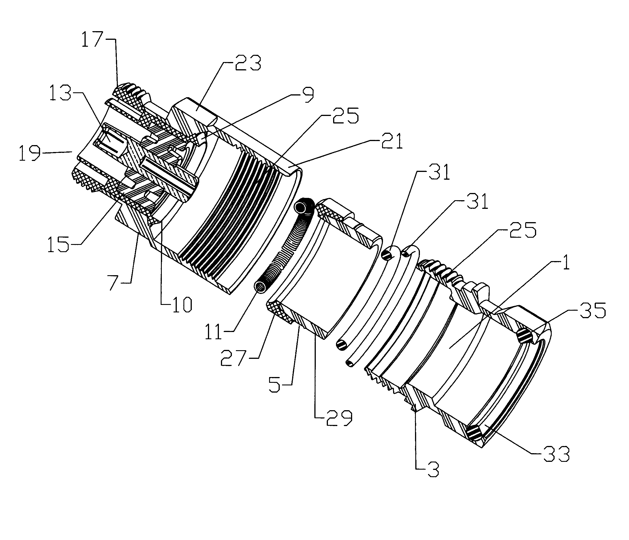
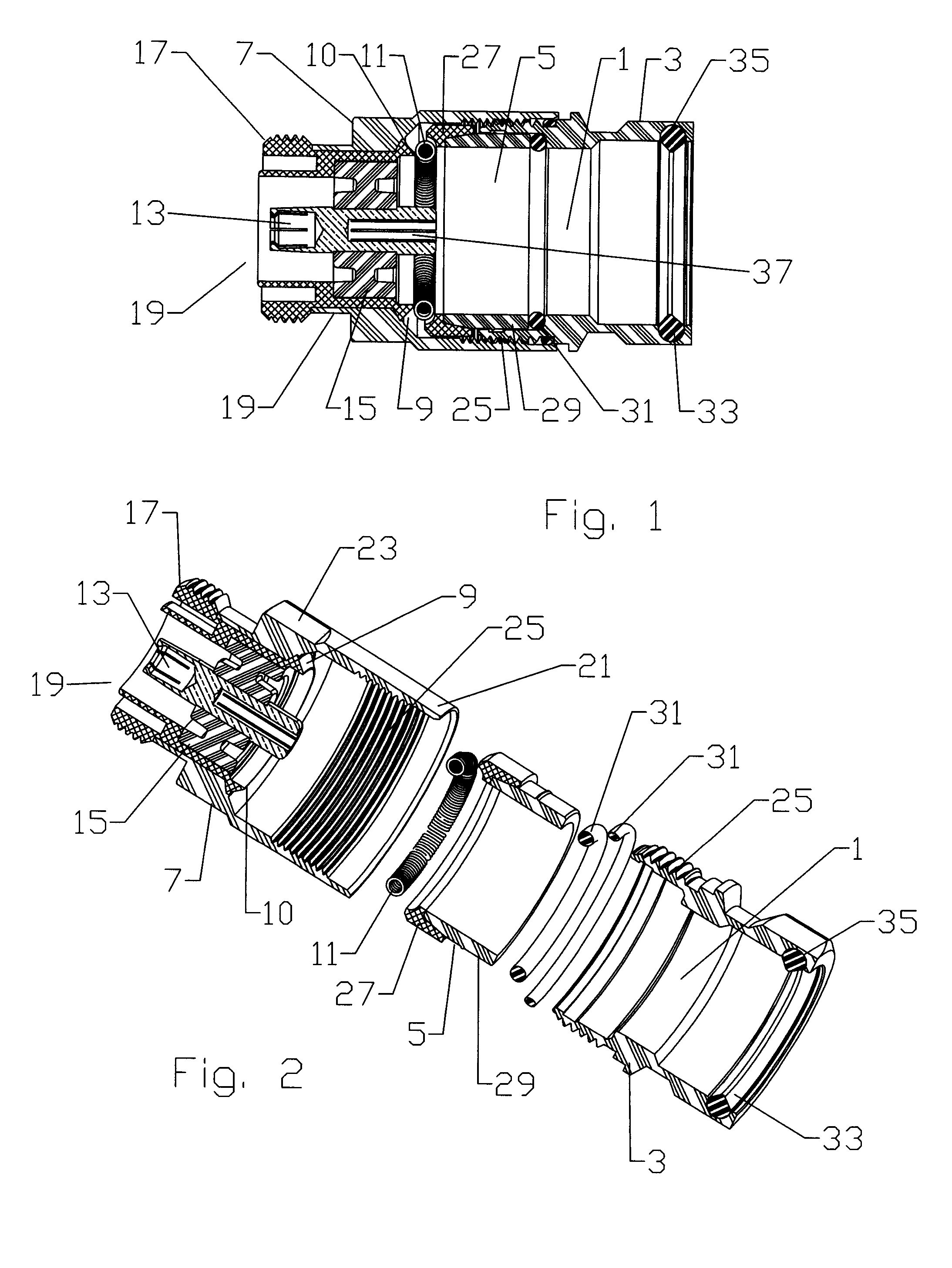
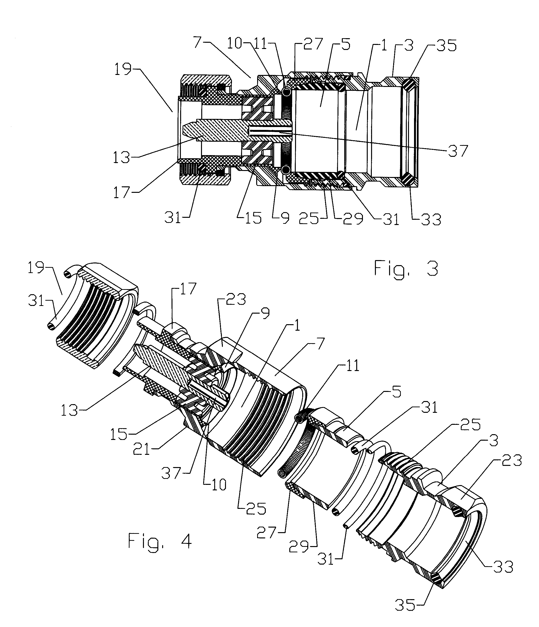
[0029]The inventor has recognized that injection moldable metal compositions, usable with conventional polymeric injection molding equipment, enables manufacture of multi-shot combination metal and polymeric material connector assemblies. Thereby, numerous manufacturing steps and the prior need for additional seals between separate elements may be eliminated to realize a significant materials and manufacturing cost savings.
[0030]An example of an injection moldable metal composition is “Xyloy”™ M950 available from Cool Poly, Inc. of Warwick, R.I., US. “Xyloy”™ M950 comprises an aluminum and zinc composition delivered in pellet form to injection molding equipment in the same manner as raw polymer pellets. Because the melting point of zinc is comparatively low, a combination of aluminum and zinc results in an alloy with a low enough melting point and viscosity characteristics suitable for use in polymeric injection molding machines without requiring any modification thereto. Other suit...
PUM
| Property | Measurement | Unit |
|---|---|---|
| temperature | aaaaa | aaaaa |
| melting points | aaaaa | aaaaa |
| outer diameter | aaaaa | aaaaa |
Abstract
Description
Claims
Application Information