Lighting apparatus and system for decontamination

a technology of light-emitting apparatus and decontamination system, which is applied in the direction of material analysis using wave/particle radiation, discharge tube luminescnet screen, instruments, etc., can solve the problem of not being able to effectively kill many types of organisms, and achieve the effect of accelerating damage to one or more organisms, reducing contamination, and reducing damag

Active Publication Date: 2009-11-03
INVENTIVE HLDG
View PDF25 Cites 51 Cited by
  • Summary
  • Abstract
  • Description
  • Claims
  • Application Information

AI Technical Summary

Benefits of technology

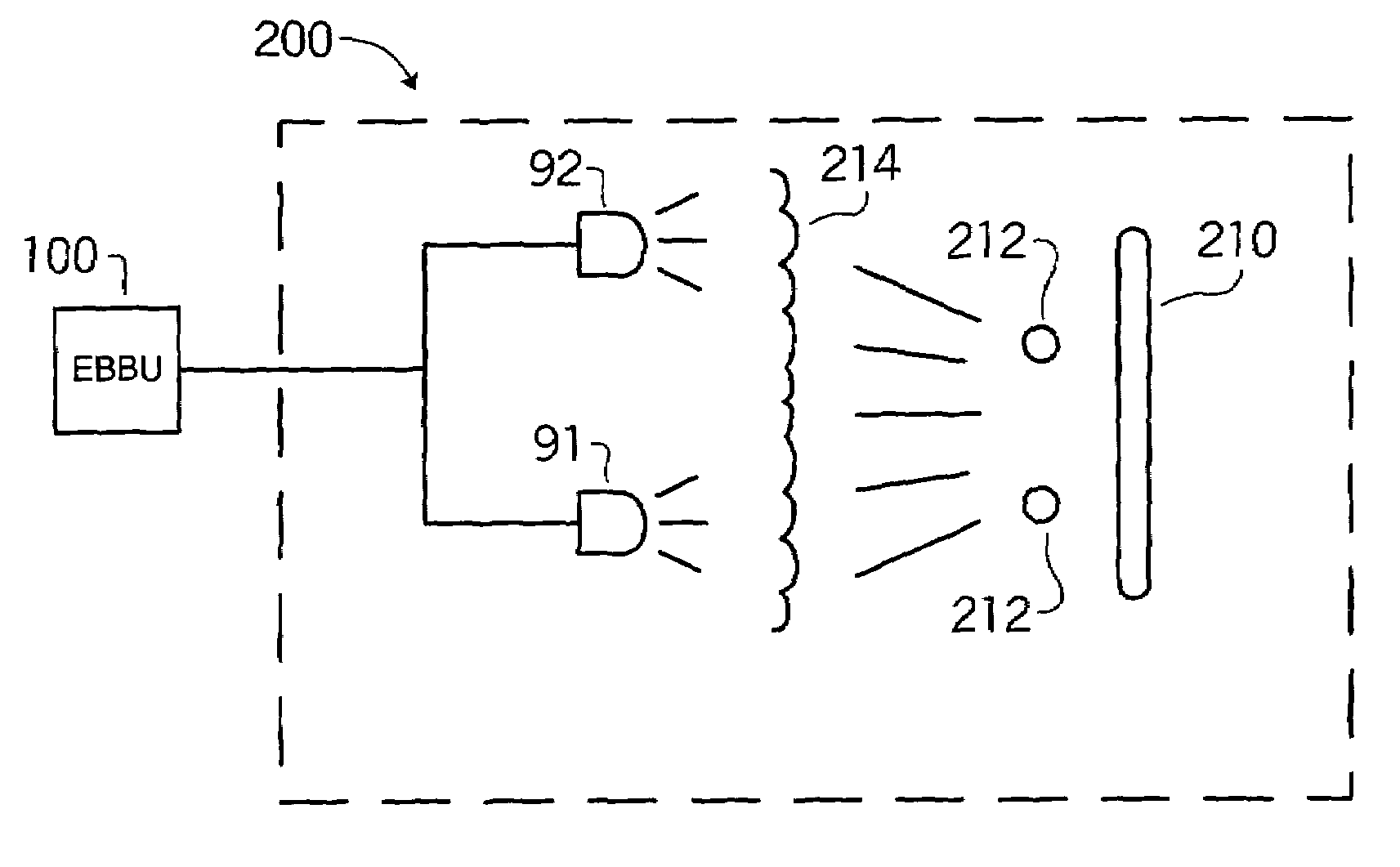
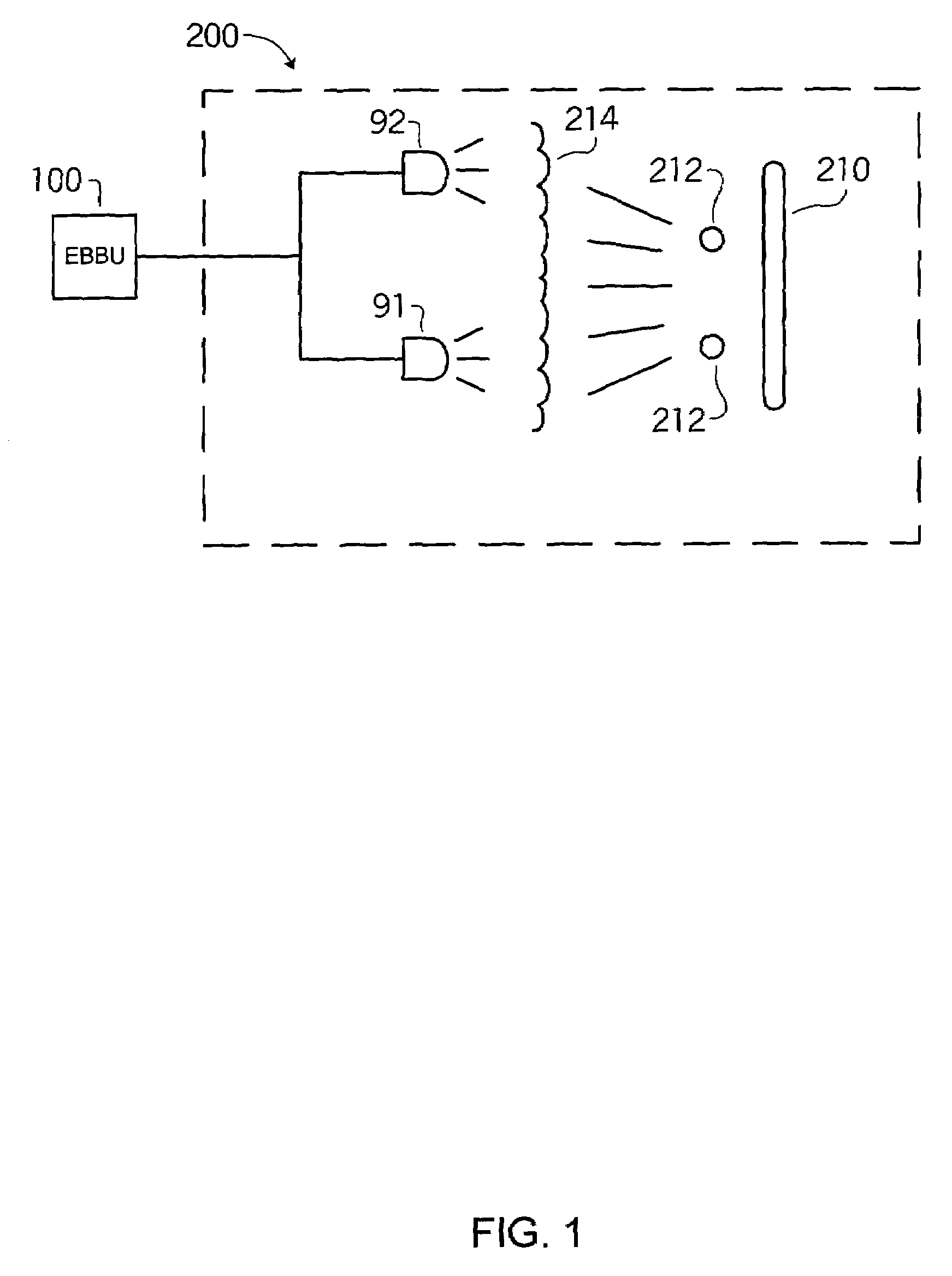
[0007]In another embodiment, a method of reducing contamination includes exposing a specimen to ultraviolet light and exposing the specimen to light at one or more selected wavelengths in the visible region. The irradiance of the light at the one or more selected wavelengths in the visible region will be sufficient to accelerate damage to one or more organisms in or on the specimen, typically, by opening a skin, outer membrane or other shell of the one or more organisms. The one or more selected wavelengths in the visible region may be selected based on the one or more organisms for which contamination reduction is desired. The exposure to ultraviolet light and the exposure to visible light may occur simultaneously. The ultraviolet light may comprise light at a wavelength of approximately 254 nm. Optionally, the method may include simultaneously exposing the specimen to light at one or more wavelengths below 200 nm at an intensity sufficient to produce ozone.

Problems solved by technology

Deadly or otherwise harmful spores, viruses and other bacteria plague our environment.
In each case, such systems typically require high power and / or long exposure to the light for decontamination to occur, and they are not effective to kill many types of organisms.

Method used


Image

  • Lighting apparatus and system for decontamination
  • Lighting apparatus and system for decontamination
  • Lighting apparatus and system for decontamination

Examples


example 1

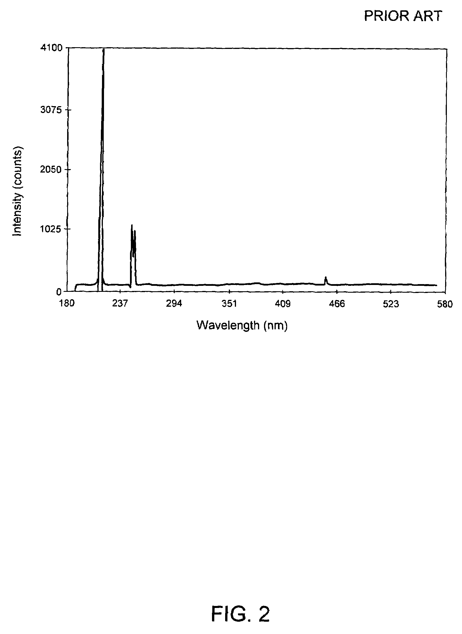
[0058]In one example, an EBBU with a germicidal lamp was tested to determine the time it would take to destroy bacillus spores. Four spore strips were exposed to targeted ultraviolet light at zero seconds, 30 seconds, 60 seconds and 120 seconds, respectively. Each spore strip was positioned approximately nine inches from the bulb. One type of spore strip included bacillus stearothermophilus and was incubated at 55° C. for 14 days prior to exposure to the light. Other spore strips included B. subrilis var. niger and was incubated at 35° C. for 14 days prior to exposure to the light. At one second, the bulb output wattage varied up to approximately 190 watts. At 30 seconds, the bulb output wattage varied between 175 watts and 285 watts. At 60 seconds, the bulb output wattage varied between 182 watts and 289 watts. At 120 seconds, the bulb output wattage varied between 171 watts and 291 watts. Irradiance levels of light emitted at approximately 405 nm and 422 nm that were similar to th...


PUM

PropertyMeasurementUnit
wavelengthsaaaaaaaaaa
wavelengthaaaaaaaaaa
wavelengthsaaaaaaaaaa

Abstract

Contamination is reduced by exposing a specimen to light, such that the light includes ultraviolet and light of wavelength in the visible region, so that the light in the visible region damages the shell of an organism and the ultraviolet light prevents reproduction of the organism.

Description

RELATED APPLICATIONS[0001]This application claims priority to, and incorporates by reference, U.S. provisional patent application No. 60 / 476,494, filed Jun. 6, 2003.TECHNICAL FIELD[0002]The present invention relates to methods and systems for decontamination. More specifically, the present invention relates to methods and systems using lighting at various frequencies and / or wavelengths to destroy spores, bacteria, other microorganisms or other living organisms such as cells or mites.BACKGROUND[0003]Deadly or otherwise harmful spores, viruses and other bacteria plague our environment. Many technologies have arisen to respond to this problem. For example, to eliminate and / or reduce the growth of bacteria in foods, various methods of irradiating food have been developed. Deadly and / or disease-causing spores can be found in other locations as well, as demonstrated by the discovery of anthrax and various letters sent through the United States mail. Such spores, bacteria, viruses and micr...

Claims


Application Information

Patent Timeline
Patent Type & Authority Patents(United States)
IPC IPC(8): H01J1/62B01J19/12A23L3/26A23L3/28A61L2/08A61L2/10
CPCA23L3/26A61L2/10A61L2/08A23L3/28
Inventor LESTICIAN, GUY J.
Owner INVENTIVE HLDG
Why Eureka
Try Eureka