
Valve prosthesis for implantation in the body and a catheter for implanting such valve prosthesis

a valve prosthesis and body technology, applied in the field of valve prosthesis, can solve the problems of difficult the inability to offer such surgery to certain people, and the limited number of heart and lung machines available in the hospital

Inactive Publication Date: 2009-11-17
EDWARDS LIFESCIENCES AG
View PDF120 Cites 628 Cited by
  • Summary
  • Abstract
  • Description
  • Claims
  • Application Information

AI Technical Summary

Benefits of technology

[0016]It is the object of the present invention to provide a valve prosthesis of the type mentioned in the introductory part, which permits implantation without surgical intervention in the body and by using a catheter technique known per se and which makes it possible for the patient to resume a substantially normal life.
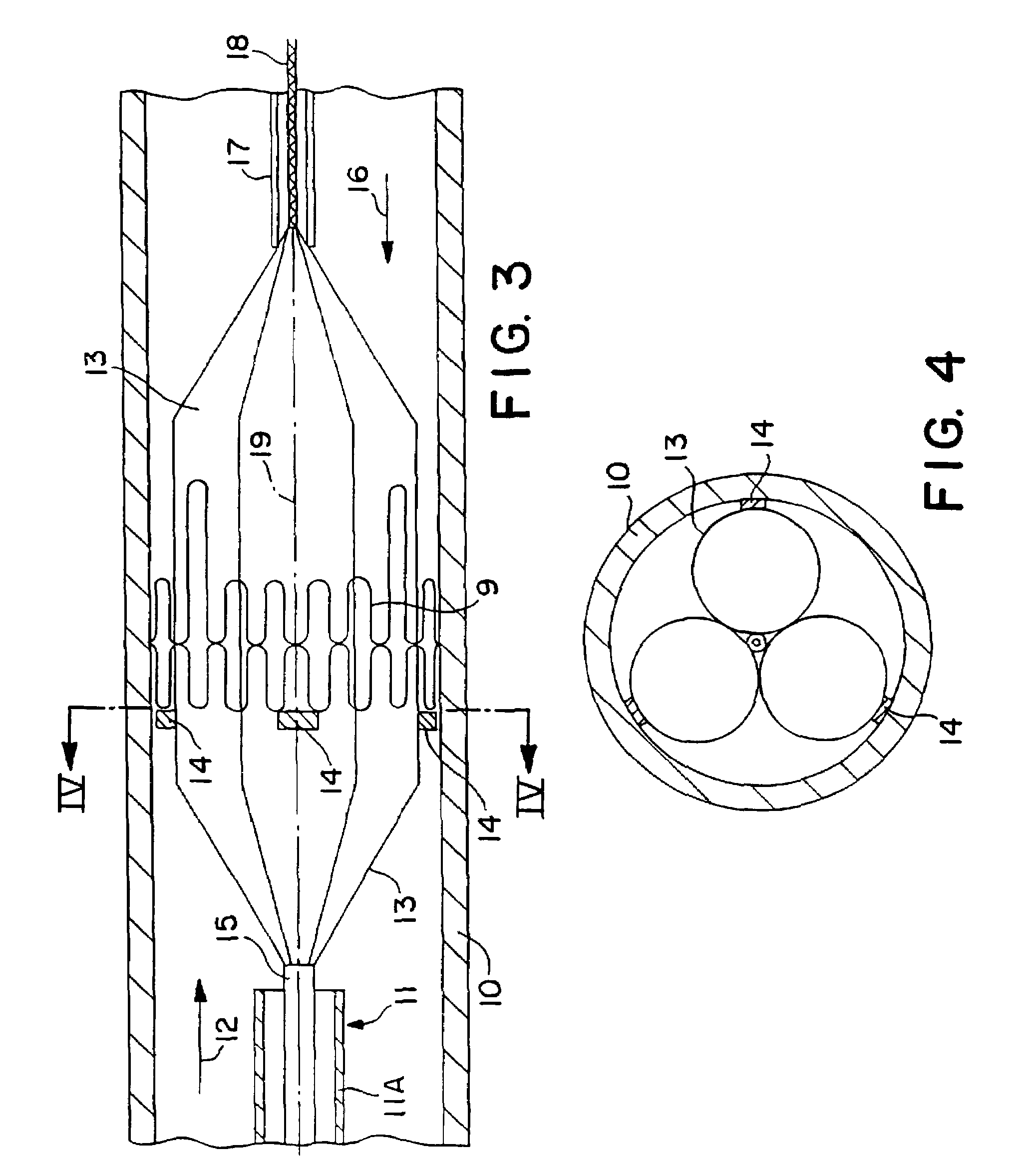
[0020]When the valve prosthesis is introduced and placed correctly, the stent is expanded by self-expansion or by means of the expansion arrangement until the stent is given an outer dimension which is slightly larger than the channel in which it is placed. As the stent is elastic, a contraction of the stent is prevented once it is expanded. The stiffness in the material of the support means contributes to maintain the expanded shape of the stent. After the expansion is made, the expansion arrangement of the catheter is contracted and the catheter can be removed from the channel. The inlet opening can subsequently be closed and the patient will then be able to resume a normal life.
[0023]In persons having varicose veins the blood flows in a wrong direction, viz. from the central veins in the center of the leg towards the superficial veins. Among other things, this is due to the changed pressure in the legs, upright working position and other conditions. A valve prosthesis according to the invention may easily be placed in the veins and prevent the flow of the blood in a wrong direction.
[0031]Different balloon catheters for implanting cores in the body are known. For instance, such balloon catheters are known from U.S. Pat. Nos. 4,856,516, 4,733,665 and 4,796,629 and from DE publication No. 2,246,526. However, the known balloon catheters have a smooth or a slightly wavy surface. The use of such balloon catheter is disadvantageous for mounting a valve prosthesis in a channel having a large flow as for instance the aorta. A large humour flow is able to displace the stent on the smooth surface of the balloon and makes an accurate positioning difficult. This drawback has been remedied with the balloon catheter according to the present invention as the profiled surface prevents a displacement of the valve prosthesis in relation to the balloon means during introduction and the subsequent inflation of the balloon means.

Problems solved by technology

However, a surgical implantation is often an exacting operation.
Due to its exacting character, it is impossible to offer such operation to certain people.
For instance, this is due to the fact that the person is physically weak because of age or illness.
Moreover, the number of heart and lung machines available at a hospital will be a substantially limiting factor.
However, this valve prostheses is not designed for implantation in the body by catheterization.
Even though the stent is slightly collapsible, it will not be suited for implantation by a catheterization procedure.

Method used


Image

  • Valve prosthesis for implantation in the body and a catheter for implanting such valve prosthesis
  • Valve prosthesis for implantation in the body and a catheter for implanting such valve prosthesis
  • Valve prosthesis for implantation in the body and a catheter for implanting such valve prosthesis

Examples


Embodiment Construction

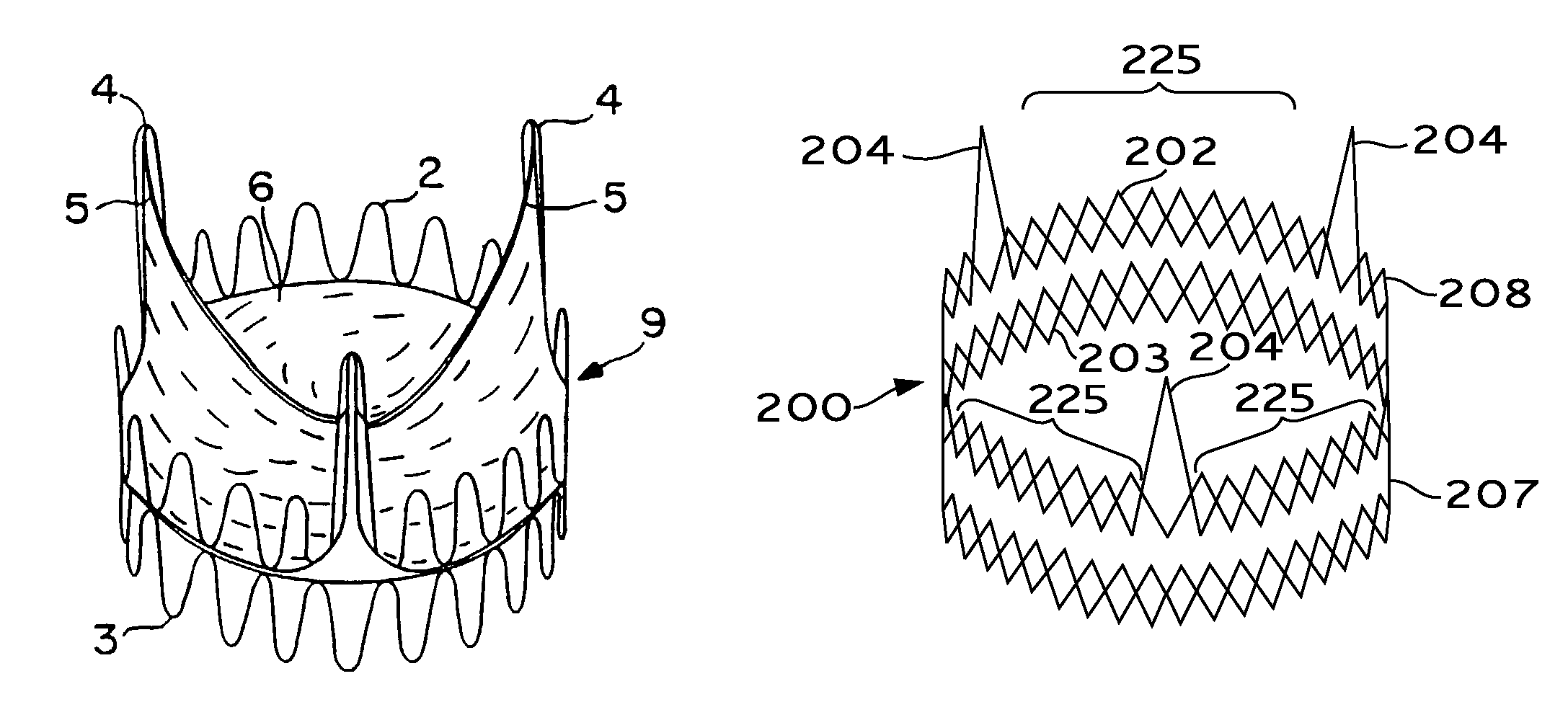
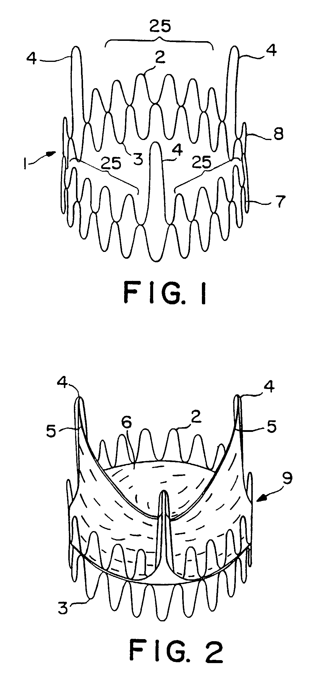
[0042]FIG. 1 shows a stent 1 made by support means in the form of two 0.55 mm surgical stainless steel wires 2,3. The wires are folded in 15 loops. Three loops 4 are 14 mm in height and are intended to secure the commissural points 5 (see FIG. 2) from a biological cardiac valve 6 which is mounted in the stent 1. The remaining loops have a height of 8 mm. These loops form circumferentially expandable sections 25 between the commissural points 5 forming commissural supports. Each of the two folded wires 2,3 is bent to form rings 7,8 which are closed by welding the ends. The two rings are placed on top of each other as will appear from FIG. 1 and they are mutually secured by means of a number of sutures (not shown). The lower ring is circumferentially expandable at least along sections thereof which correspond to the circumferentially expandable sections 25. By using a substantially cylindrical thread structure with projecting apices, a reduction in weight is obtained as compared to a ...


PUM


Abstract

A valve prosthesis for implantation in the body by use of a catheter includes a stent made from an expandable cylinder-shaped thread structure including several spaced apices. The elastically collapsible valve is mounted on the stent as the commissural points of the valve are secured to the projecting apices. The valve prosthesis can be compressed around balloons of the balloon catheter and inserted in a channel, for instance, in the aorta. When the valve prosthesis is placed correctly, the balloons are inflated to expand the stent and wedge it against the wall of the aorta. The balloons are provided with beads to ensure a steady fastening of the valve prosthesis on the balloons during insertion and expansion. The valve prosthesis and the balloon catheter make it possible to insert a cardiac valve prosthesis without a surgical operation involving opening the thoracic cavity.

Description

CROSS REFERENCE TO RELATED APPLICATION[0001]This application is a continuation of U.S. patent application Ser. No. 09 / 514,426, filed Feb. 28, 2000, (now U.S. Pat. No. 6,582,462), which is a continuation of U.S. patent application Ser. No. 09 / 026,574, filed Feb. 20, 1998 (now U.S. Pat. No. 6,168,614), which is a continuation of U.S. patent application Ser. No. 08 / 955,228, filed Oct. 21, 1997 (abandoned), which is a divisional of U.S. patent application Ser. No. 08 / 801,036, filed Feb. 19, 1997 (issued as U.S. Pat. No. 5,840,081 on Nov. 24, 1998), which is a continuation of U.S. patent application Ser. No. 08 / 569,314, filed Dec. 8, 1995 (abandoned), which is a continuation of U.S. patent application Ser. No. 08 / 352,127, filed Dec. 1, 1994 (abandoned), which is a divisional of U.S. patent application Ser. No. 08 / 261,235, filed Jun. 14, 1994 (now U.S. Pat. No. 5,411,552), which is a continuation of U.S. patent application Ser. No. 07 / 961,891, filed Jan. 11, 1993 (abandoned), which is a n...

Claims


Application Information

Patent Timeline
Patent Type & Authority Patents(United States)
IPC IPC(8): A61F2/24A61F2/90A61F2/88
CPCA61F2/2418A61F2/2433A61F2/2475A61F2230/0013Y10S623/904A61F2220/005A61F2220/0058Y10S623/90
Inventor ANDERSEN, HENNING RUDHASENKAM, JOHN MICHAELKNUDSEN, LARS LYHNE
Owner EDWARDS LIFESCIENCES AG
Learn More