Liquid crystal display device

a display device and liquid crystal technology, applied in static indicating devices, optics, instruments, etc., can solve problems such as lowering display quality, and achieve the effects of lowering display quality, high resistance, and high quality

Inactive Publication Date: 2009-11-17
PANASONIC LIQUID CRYSTAL DISPLAY CO LTD +1
View PDF7 Cites 8 Cited by
  • Summary
  • Abstract
  • Description
  • Claims
  • Application Information

AI Technical Summary

Benefits of technology

[0010]In the time-division-driving, two or more drain lines are formed into one set, and a voltage is written in the respective drain lines by performing the time division of one horizontal period of one output from the drain driver IC chip and hence, there exists a period in which the drain line assumes an electrically floating state in the midst of one horizontal period. A common line layer (common layer) which is formed of an ITO layer has the high resistance and hence, there may be a case that a target common line voltage is not obtained at a remote end of the common line before the drain line assumes the floating state. Here, during a period in which the gate line assumes an ON level and the drain line assumes a floating state, when the common line (or common electrode) voltage is changed, the voltage of the drain line or the voltage of the pixel electrode is changed due to the capacitive coupling. Accordingly, when the common line voltage is changed during the period that the gate line assumes an OFF level, the pixel voltage and the drain line voltage are changed due to the capacitive coupling and hence, the pixel voltage is displaced from the target voltage thus giving rise to the lowering the display quality. The similar phenomenon may occur when the storage line is changed. Accordingly, it is possible to obtain the display of high quality by suppressing the change of the pixel voltage.
[0026]By additionally providing the capacitance between the drain lines and other fixed potentials, it is possible to reduce the voltage fluctuation of the pixel electrodes and the voltage fluctuation of the drain lines generated by the capacitive coupling of the common electrodes or the common lines. Further, the pixel voltage difference between the near end portions and the remote end portions of the common lines can be reduced. As a result, it is possible to obtain the image display having the stabilized high quality.

Problems solved by technology

Accordingly, when the common line voltage is changed during the period that the gate line assumes an OFF level, the pixel voltage and the drain line voltage are changed due to the capacitive coupling and hence, the pixel voltage is displaced from the target voltage thus giving rise to the lowering the display quality.

Method used


Image

  • Liquid crystal display device
  • Liquid crystal display device
  • Liquid crystal display device

Examples


embodiment 1

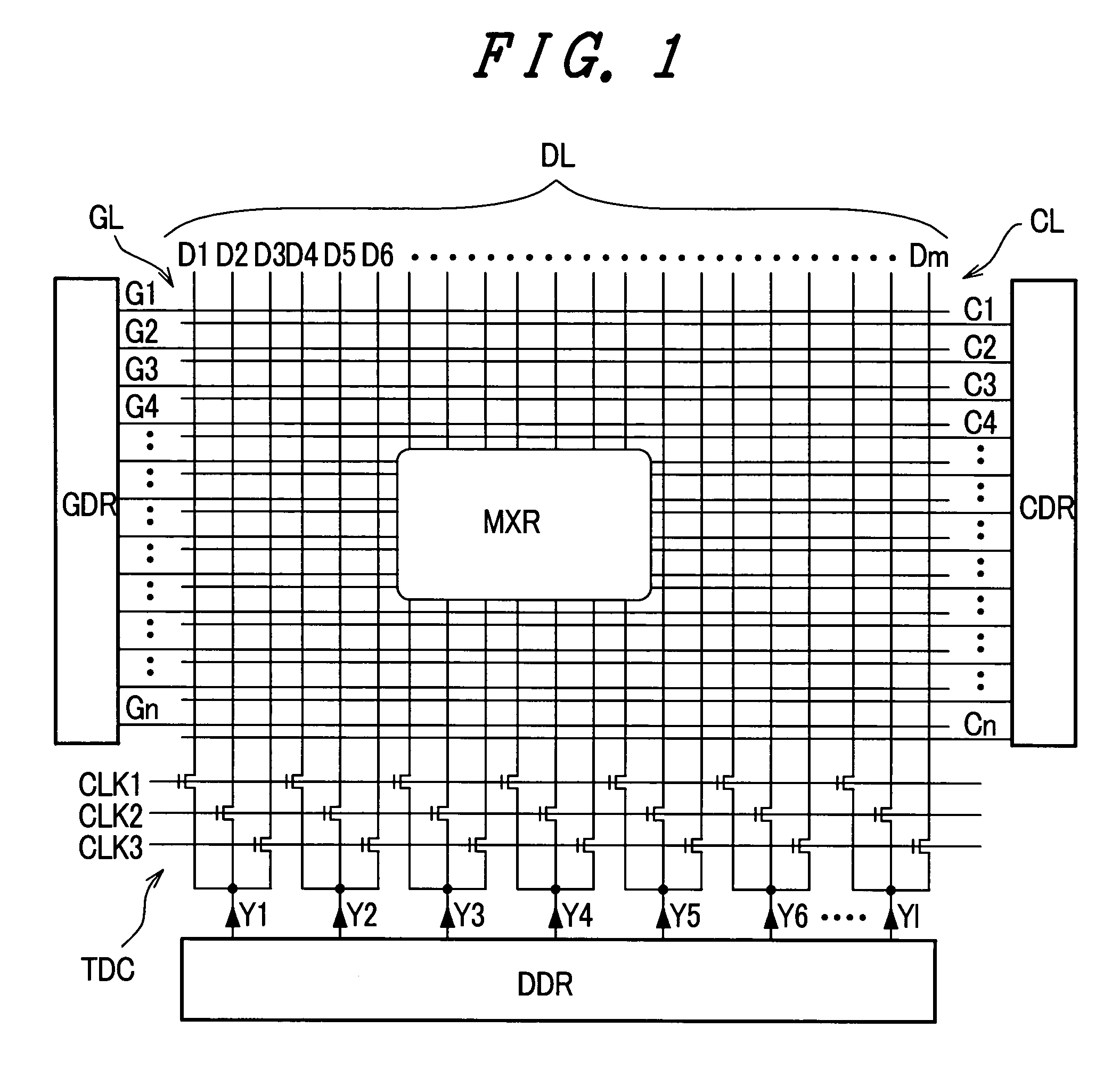
[0046]FIG. 1 is an explanatory view showing a constitutional example of a liquid crystal display device of the present invention which performs the time-division driving. In FIG. 1, on a pixel matrix portion, that is, on a display region MXR, gate lines GL (G1, G2, . . . Gn) and drain lines DL (D1, D2, . . . Dm) are arranged in an intersecting manner. The plurality of gate lines GL extend in one direction (the lateral direction in FIG. 1) and are arranged in parallel in another direction (the longitudinal direction in FIG. 1) which intersects one direction. The plurality of drain lines DL extend in the above-mentioned another direction and are arranged in parallel in the above-mentioned one direction. Corresponding to intersecting portions of the gate lines GL and the drain lines DL, a plurality of pixels are arranged in a matrix array thus forming the above-mentioned display region MXR. Each pixel includes a thin film transistor (TFT), wherein a gate of the thin film transistor of ...


PUM

PropertyMeasurementUnit
widthaaaaaaaaaa
electroluminescenceaaaaaaaaaa
electric fieldsaaaaaaaaaa

Abstract

The present invention provides a liquid crystal display device which can obtain a high image quality display by suppressing the fluctuation of a pixel voltage. Along a large number of drain lines which are driven in a time-division manner, a portion of gate line is extended and an additional capacitance is formed by an extending portion of the gate line which has fixed potential and the drain line.

Description

[0001]The present application claims priority from Japanese application JP2003-432389 filed on Dec. 26, 2003, the content of which is hereby incorporated by reference into this application.BACKGROUND OF THE INVENTION[0002]The present invention relates to an active matrix type display device, and more particularly is suitably applicable to a liquid crystal display device which performs time-division driving of drain lines.[0003]As a display device which is capable of performing a high-definition color display for a mobile phone, a notebook type computer, a display monitor or the like, various types of flat panel type display devices including a liquid crystal display device which uses a liquid crystal panel, an organic electroluminescence display device (organic EL display device) which uses electroluminescence (particularly organic electroluminescence) element, a field emission type display device (FED) which uses field emission element and the like have been already put into practi...

Claims


Application Information

Patent Timeline
Patent Type & Authority Patents(United States)
IPC IPC(8): G02F1/1343G02F1/133G02F1/136G02F1/1362G02F1/1368G09G3/20G09G3/36H01L29/786
CPCG02F1/136213G09G3/3648G02F1/134363G09G3/3614G09G2320/0233G09G3/3688G09G2310/0297
Inventor FUJIOKA, TAKAHIROHIRAGA, KOJIKUBOTA, TAKEHIKO
Owner PANASONIC LIQUID CRYSTAL DISPLAY CO LTD
Why Eureka
Try Eureka