
Compact robotic painting booth

a robotic painting and compact technology, applied in the field of robotic systems, can solve the problems of robot stopping, no protection for a person in the safety zone, and the need to disable the light curtain

Active Publication Date: 2009-11-24
FANUC ROBOTICS NORTH AMERICA
View PDF8 Cites 13 Cited by
  • Summary
  • Abstract
  • Description
  • Claims
  • Application Information

AI Technical Summary

Benefits of technology

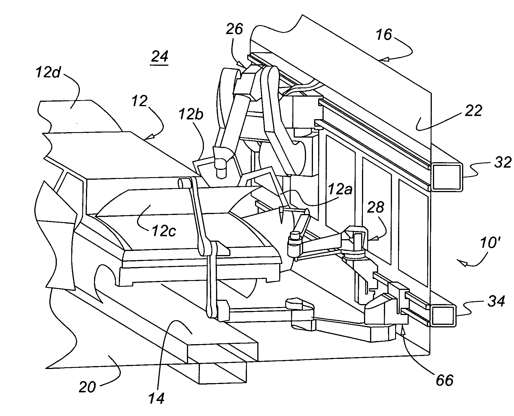
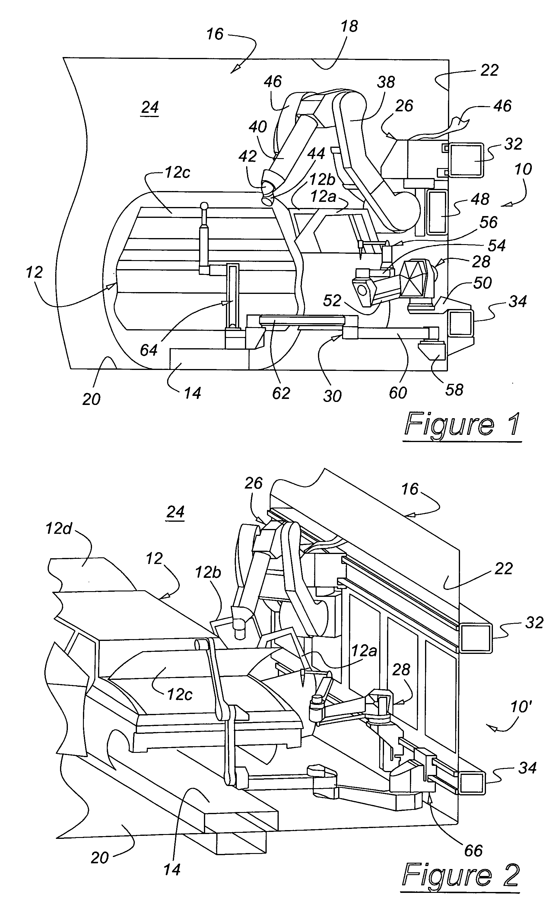
"The present invention is a robotic painting system for painting surfaces of a vehicle body, including the interior surfaces of doors, hoods, and decks. The system includes a paint robot, a door opener robot, and a hood / deck opener robot mounted on rails that extend along a conveyor that carries the body through the booth. The paint robot operates to paint the surfaces of the vehicle body using a bell cup applicator or the like. The door opener robot moves a vehicle door into a position so that the paint robot may paint its interior and exterior surfaces. The hood / deck opener robot moves a hood and / or a deck lid of the vehicle body into a position so that the paint robot may paint its interior and exterior surfaces. The system allows for the use of a compact indirect charge system for waterborne paint and direct charge fast color change systems for solvent and water-based materials. The system can operate in a reliable manner with similar maintenance intervals to those of other automotive class rotary atomizers. The paint system controller controls operation of a dump valve and vent valve, arranged in parallel with the dump valve, such that the vent valve is opened during a color change operation to vent air through narrow flow passages to a dump collector. This arrangement and control provides an advantage since the dump valve must be closed at precisely the right time in the process to gain the maximum benefit of venting all the air in the system, while preventing paint from being wasted through the dump passage."

Problems solved by technology

If the robot travels too far down the rail, it will trip the limit switch and cause the robot to stop before the arm enters the safety zone.
But the light curtain must be disabled when the vehicle body is present because the vehicle body would otherwise break the light beam as the body passes along the conveyor path.
When the light curtain is disabled to allow a vehicle body to pass, it doesn't offer any protection to a person in the safety zone.
paint utility line failures are costly and time consuming to repair.

Method used


Image

  • Compact robotic painting booth
  • Compact robotic painting booth
  • Compact robotic painting booth

Examples


third embodiment

[0058]In FIG. 12, there is shown the present invention for isolating the conductive components. The circulation system 308, which includes a color change system, is connected to a source of solvent 330 and a source of pressurized air 332. The circulation system 308 communicates through an electrically isolated line 310′ to the component mixing system 316′, which can be a static mixing tube or another device used in multi-component delivery systems. A canister isolation system is used for the nonconductive material, such as resin. If a non-conductive component is used for one of the materials, a more traditional means such as a gear pump or flowmeter 312′ can be used to deliver that fluid to the multi-component mixing system 316′.

[0059]The mixed material can be applied by any direct charge electrostatic paint applicator 318′, such as a rotary atomizer, where the paint and / or applicator are charged (electrostatics), or an electrostatic gun applicator.

[0060]pressure transducers 314′, w...

fourth embodiment

[0061]There is shown in FIG. 13 the present invention for isolating the waterborne or substantially conductive component when only the waterborne or substantially conductive material is provided and no second component is added. This is a batch painting system.

[0062]The paint circulation system 308 delivers paint to a color valve stack. Different colors of paint are supplied to a color changer 326, which delivers the paint to a pair of paint valves 328, one of which supplies paint to one of the canisters 320, 321. A pair of canisters 320, 321 alternately supplies paint through an isolation manifold 322 to a robot-mounted applicator 324. Canister 320 is shown in a filling position where paint is delivered to canister 320 through valve 328 at a docking station. Canister 321 is shown in its painting position. Each canister consists of a stainless steel canister sleeve, canister body, piston, ram, ball screw, motor, and drive frame. The painting canister 321 must be suitably undocked fr...


PUM

PropertyMeasurementUnit
diameteraaaaaaaaaa
diameteraaaaaaaaaa
diameteraaaaaaaaaa

Abstract

A system for painting an article, such as an automotive vehicle body, includes a painting booth, a conveyor for transporting articles through the painting booth, a first rail located beside and extending along the conveyor, a second rail located beside and extending along the conveyor at a lower elevation than an elevation of the first rail, a paint robot including an articulating arm mounted on the first rail for displacement along the first rail, a panel opener robot mounted on the second rail for displacement along the second rail such that the paint robot and the panel opener robot can move past each other on the rails without interference.

Description

CROSS-REFERENCE TO RELATED APPLICATIONS[0001]This application claims the benefit of U.S. Provisional Application No. 60 / 517,767, filed Nov. 6, 2003, and 60 / 583,078, filed Jun. 25, 2004, the entire disclosures of which are incorporated herein by reference.BACKGROUND OF THE INVENTION[0002]The present invention relates generally to a robotic system for processing an article in serial high-volume production. More particularly, the invention pertains to minimizing the size of a painting booth containing a robotic system used to paint a motor vehicle body.[0003]The safety zone is an area in a painting booth where people could be present while a robot, mounted for movement along a rail beside a conveyor, operates. Frequently people are present in the booth to view the robot in operation. It is conventional practice to use a limit switch, mounted on the rail, to stop the robot at a fixed location on the rail and prevent an articulating robot arm from entering the safety zone located at the ...

Claims


Application Information

Patent Timeline
Patent Type & Authority Patents(United States)
IPC IPC(8): B05B3/00B05B3/02B05D1/02B05B15/12B05B5/16B05B12/14B05B13/04B25J5/02B25J9/00B25J9/16B25J19/00
CPCB05B12/149B05B13/0292B05B13/0431B05B13/0452B05B15/025B25J5/02B25J9/0093B25J9/1676B25J19/0025B25J19/06B05B5/1633B05B5/1616G05B2219/45013B05B12/14B05B12/1418B05B15/12G05B2219/39083B05B15/55B05B16/00
Inventor CLIFFORD, SCOTT J.KOWALSKI, JAMES M.ROLA, MARTIN D.BARTLETT, DONALD S.COPIOLI, PAUL D.GERDS, II, JAMES B.GORA, MARCINMCCLOSKEY, STAN H.
Owner FANUC ROBOTICS NORTH AMERICA
Learn More