Voltage overshoot protection

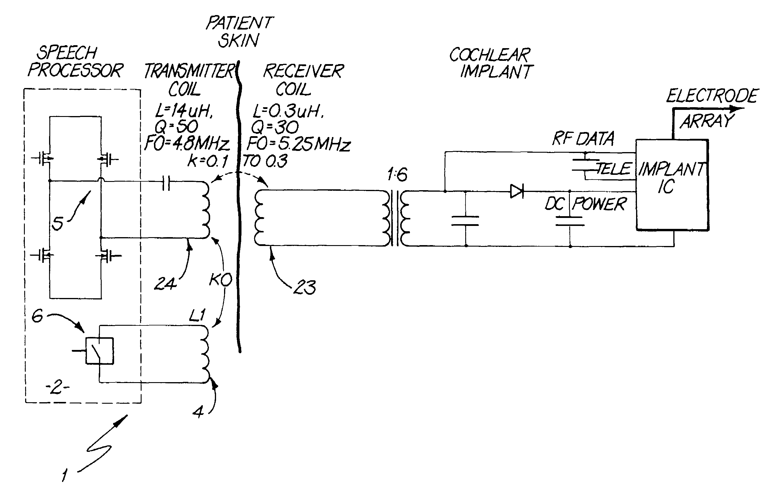
a technology of voltage overshoot and protection, applied in the direction of subscriber station connection selection arrangement, transmission, indirect connection of subscriber, etc., can solve the problems of inability to convert, error, modulation depth of waveform received in the receiver, etc., to increase the tuned frequency of the transmitter coil and accelerate the decay of ringing

Active Publication Date: 2009-11-24
COCHLEAR LIMITED
View PDF3 Cites 7 Cited by
  • Summary
  • Abstract
  • Description
  • Claims
  • Application Information

AI Technical Summary

Benefits of technology

[0035]The present invention avoids the voltage overshoot problem of the prior art Tri-State approach by utilising a damping arrangement, so as to provide the desired improved modulation depth in the received waveform. This selectively increases the tuned frequency of the transmitter coil to provide fast decay of ringing in the receiver coil. In a preferred form, the damping is provided by a closely coupled auxiliary coil, operated when the momentary state of the data is a zero.

Problems solved by technology

A cochlear implant is used where the hair cells of the cochlea have been damaged to the extent that they are no longer able to convert the mechanical vibration of the cochlea fluid into an electrical signal.
A problem with such inductive communication links is that errors can occur when the modulation depth of the waveform received in the receiver coil falls below a certain threshold.
This ‘tri-state’ function reduces the effective quality factor of the transmitter coil, increases the resonance frequency, thus creating a higher frequency post RF-burst ringing that decays quickly.
However, a drawback of the prior art tri-state function is that an excessive voltage overshoot is generated when the output switches of the RF drivers are open-circuited.
This voltage overshoot can affect the reliability of the integrated circuit since the output switches may be overstressed from being operated outside the maximum operating voltage specified by the integrated circuit manufacturer.
Further, this overstressing can gradually weaken, and eventually permanently damage the output switches.
Further, voltage waveform clamping and current conduction through the diodes defeats the purpose of the tri-state function until the signal drops below the clamping point.

Method used


Image

  • Voltage overshoot protection
  • Voltage overshoot protection
  • Voltage overshoot protection

Examples


Embodiment Construction

[0042]It will be appreciated that whilst present invention will be principally described with reference to cochlear implants, the principles of the present invention may be applied in relation to many other types of inductive links, and in particular to other types of implanted medical devices. It is applicable whether or not power and data, or data alone, are being transmitted. It is also applicable whether the link operates more or less continuously, or in a more sporadic or occasional mode.

[0043]Before describing the features of one implementation of the present invention in detail, it is convenient to further describe the construction and overall operation of one example of a cochlear implant system. It will be understood that the present invention could be applied to other types of cochlear implants.

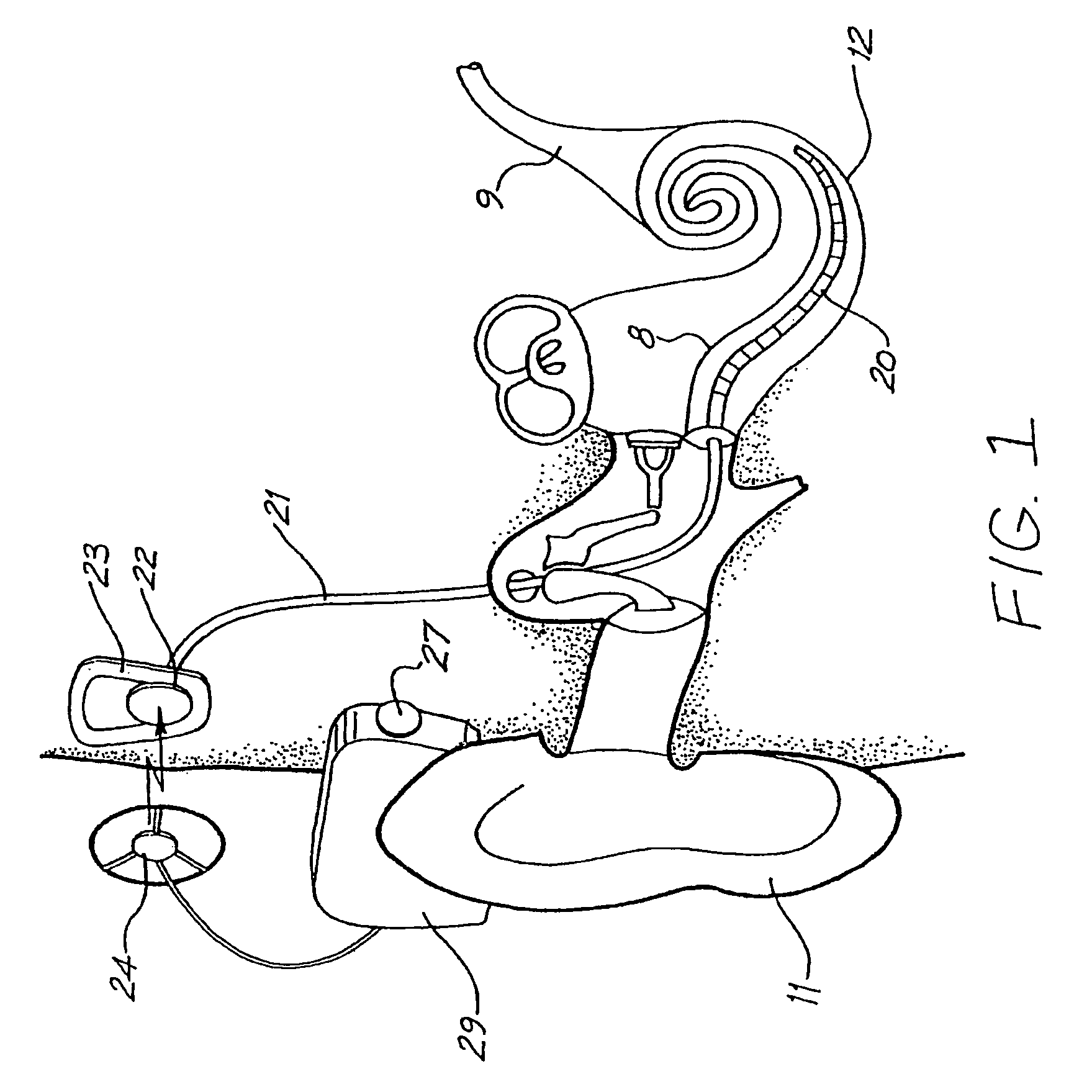
[0044]Referring to FIG. 1, the external sound processor device 29 includes an on-board microphone 27 and is generally configured to fit behind the outer ear 11, as shown. The sound ...


PUM


Abstract

A transmission circuit for an RF inductive link, particularly for an implanted device such as a cochlear implant. In a preferred form, the transmission circuit 1 includes a transmitter coil 24 and a damping device, including an auxiliary coil 4 and switch 6. The switch is operated to close the coil circuit when data zeros are transmitted. This has the advantage of improving modulation depth without placing stress on the RF driver output switches.

Description

CROSS-REFERENCE TO RELATED APPLICATIONS[0001]This application claims priority from Australian Provisional Patent Application No. 2003905729 filed on Oct. 20, 2003, the contents of which is incorporated herein by reference.BACKGROUND[0002]1. Field of the Invention[0003]The present invention relates to inductive data links, and particularly but not exclusively to data links and transmission protocols that are used in conjunction with implantable medical devices.[0004]2. Related Art[0005]Inductive links are used in many applications, but have particular application to implanted medical devices such as pacers, cochlear implants and other neural stimulators, and other types of devices. They allow for data and / or power to be transmitted to a device which is wholly implanted from an external system, without requiring a cable or connection to pass through the skin.[0006]Hearing aids and cochlear implants are useful in restoring the sensation of hearing to hearing impaired individuals. This ...

Claims


Application Information

Patent Timeline
Patent Type & Authority Patents(United States)
IPC IPC(8): H04B5/00
CPCA61N1/3787A61N1/36032A61N1/36038
Inventor IBRAHIM, IBRAHIM
Owner COCHLEAR LIMITED
Why Eureka
Try Eureka