
Method and system to perform energy-extraction based active noise control

a technology of energy extraction and active noise, applied in adaptive control, process and machine control, instruments, etc., can solve the problems of difficult to achieve the effect of reducing structural and acoustic energy, avoiding noise pollution, and avoiding noise pollution

Inactive Publication Date: 2009-11-24
ADMINISTATOR OF THE NAT AERONAUTICS & SPACE ADMINISTATION UNITED STATES OF AMERICA AS REPRESENTED BY THE +1
View PDF1 Cites 6 Cited by
  • Summary
  • Abstract
  • Description
  • Claims
  • Application Information

AI Technical Summary

Benefits of technology

"The invention provides a way to reduce noise and vibration in enclosures like aircraft, vehicles, and industrial equipment. It uses compensators and feedback control to make the system \"passive\" and reduce the energy in the enclosure. The method involves creating a mathematical model of the plant and designing compensation to make it passive. The system is then checked to ensure its passivity is preserved. The invention can make quieter and more stable equipment, improving performance and comfort."

Problems solved by technology

If it did, then it would be a feedback scenario with a danger of closed-loop instabilities.
This meant that the schemes could be successfully implemented only with unidirectional microphones and speakers.
In general, these conditions are very stringent.
This remedy, however, did not alleviate the problems as the controllers were very sensitive to the implementation and finite digit arithmetics and had to be implemented with on-line adaptation schemes.
However, one important drawback of the prior feedforward strategies that are used is the necessity of an on-line adaptation, not due to the nature of the system (acoustic duct) but due to the nature of the controller itself.
Another difficulty with feedforward schemes is to ensure that the adaptive control algorithm will always converge.
Most algorithms guarantee convergence with known model, known controller order, and known persistency of excitation but, unfortunately, such ideal conditions are very hard to meet.
The need to use high performance DSPs for the computationally intensive on-line adaption schemes results in an expensive solution and the lack of robustness can make the noise worse in the event of small deviations.
During this time, research efforts extended to a multitude of problems, including such items as investigation of structure-borne noise, acoustic radiation from structures, reduction of noise in ducts and enclosures, and acoustic-structure interaction.
Although some earlier successful solutions to structure-borne sound used multiple microphones and loudspeakers, subsequent studies showed that loudspeakers alone are not very efficient in controlling structure-borne sound.
In spite of difficulties, a number of approaches have succeeded in feedback control of reverberant enclosures but they are restricted primarily to the low-frequency bands.
Additionally, much of the experimental work was restricted to small size cavities.
The major hurdles in successful implementation of feedforward methods included availability of a reference signal having strong correlation to the noise source, necessity of online adaptation, and lack of controller robustness.
For example, for structure-borne sound in aircraft it is difficult to obtain a reference signal which is strongly correlated with the noise producing mechanism.
This makes feedforward control very ineffective.
However, designing controllers for acoustic systems is very challenging since there is no natural roll-off at high frequencies and the systems are modally very rich.
Although the feedback control methodology has great potential, it has several obstacles to overcome.
One problem with many feedback control techniques used is that the noise attenuation can be guaranteed only locally (i.e., only at the sensor locations) and not uniformly in space and / or frequency.
In fact, the noise levels can go high at some other locations although there is attenuation at the sensor locations.

Method used


Image

  • Method and system to perform energy-extraction based active noise control
  • Method and system to perform energy-extraction based active noise control
  • Method and system to perform energy-extraction based active noise control

Examples


Embodiment Construction

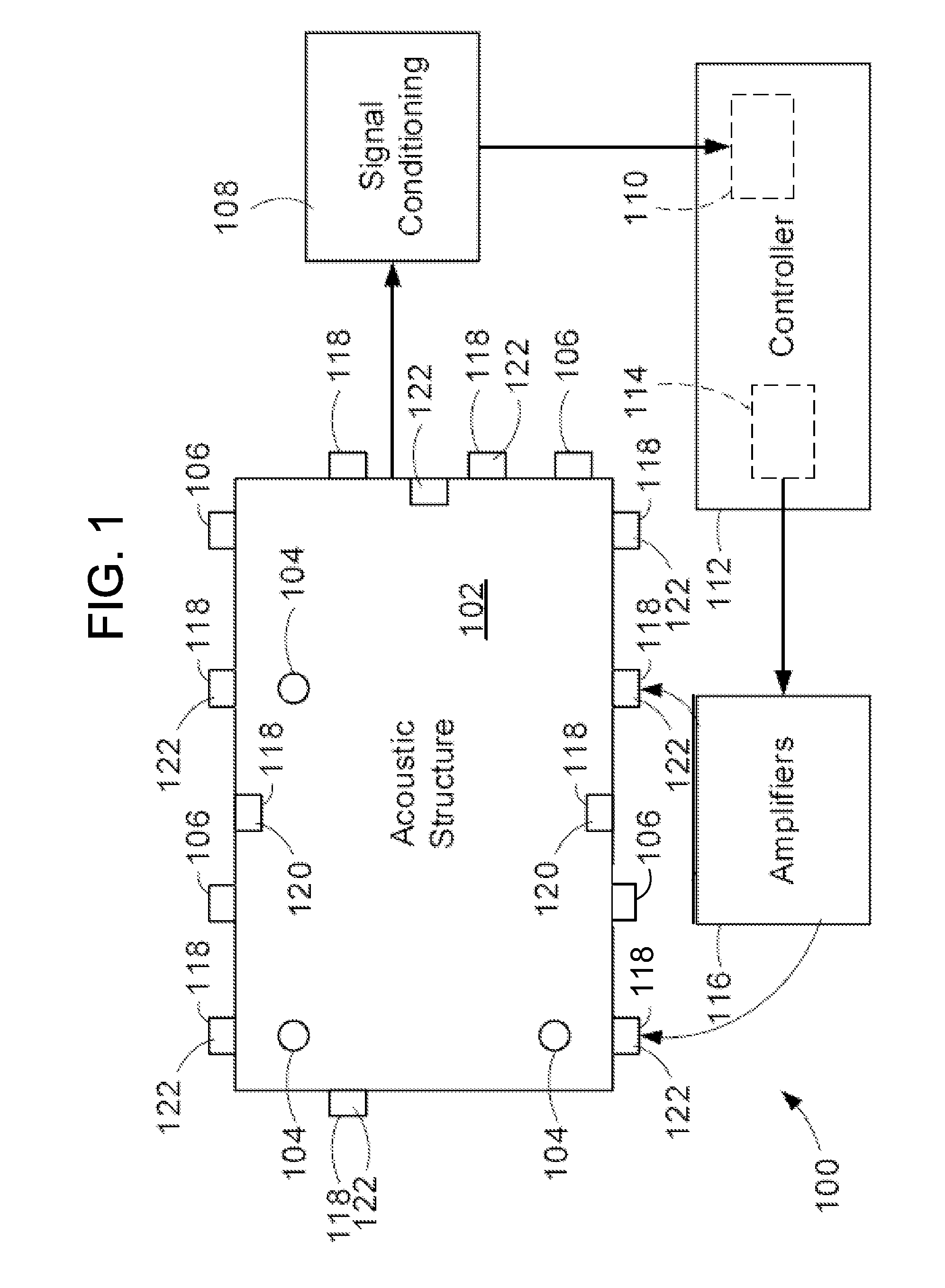
[0025]The invention extracts acoustic energy and structural energy in acoustic enclosures. The system utilizes acoustic sensors and actuators (e.g., microphones and loudspeakers) and actuators (e.g., accelerometers and piezoelectric devices) to reduce the acoustic energy and structural energy of the system. A compensator is designed to render the open-loop system passive in the sense of mathematical system theory. A positive-real feedback controller is then designed. The resulting system is typically a multi-input multi-output feedback control system that incorporates the passifier and the positive-real controller. The system can achieve uniform (in space and frequency) broadband reduction in noise and vibration levels in the enclosures. As a result, quieter aircraft fuselages, vehicles, vacuum cleaners, washers, dryers, lawn and garden equipment (e.g., power blowers, lawn mowers, snow blowers, etc.), and other industrial / household machinery such as grinding machines, milling machin...


PUM


Abstract

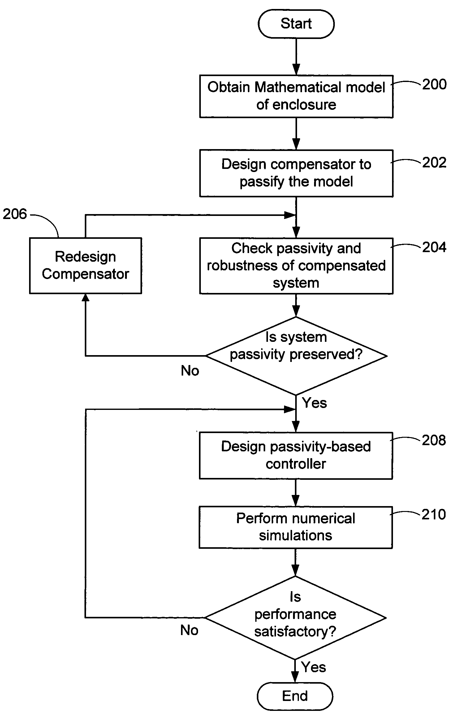
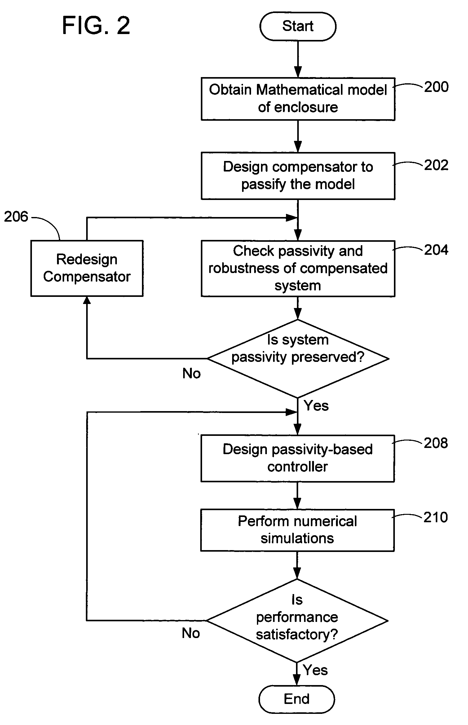
A method to provide active noise control to reduce noise and vibration in reverberant acoustic enclosures such as aircraft, vehicles, appliances, instruments, industrial equipment and the like is presented. A continuous-time multi-input multi-output (MIMO) state space mathematical model of the plant is obtained via analytical modeling and system identification. Compensation is designed to render the mathematical model passive in the sense of mathematical system theory. The compensated system is checked to ensure robustness of the passive property of the plant. The check ensures that the passivity is preserved if the mathematical model parameters are perturbed from nominal values. A passivity-based controller is designed and verified using numerical simulations and then tested. The controller is designed so that the resulting closed-loop response shows the desired noise reduction.

Description

STATEMENT REGARDING FEDERALLY SPONSORED RESEARCH AND DEVELOPMENT[0001]This invention was made in part with Government support under Grant Number NCC-1-01039 awarded by NASA and Grant Numbers 0196198 and 0301740 awarded by the NSF. The Government may have certain rights in this invention.FIELD OF THE INVENTION[0002]This invention pertains to noise suppression, and more particularly, relates to active noise control.BACKGROUND OF THE INVENTION[0003]Sound is a longitudinal wave phenomenon. Interference between waves has been known and observed since the time of Sir Isaac Newton. Active suppression of noise has been a goal for many decades. The potential applications of active noise suppression are many, ranging from aircraft cabins to automobile interiors to medical equipment (e.g., dentist drills, operating rooms, etc.) to buildings to household machinery such as vacuum cleaners, lawn mowers, snow blowers, washers, dryers, etc. The concept of wave dynamics and the ability of electronic...

Claims


Application Information

Patent Timeline
Patent Type & Authority Patents(United States)
IPC IPC(8): G06F7/60
CPCG10K11/178G05B13/042G10K11/17875G10K11/17813G10K11/17857G10K11/1783G10K11/17817
Inventor KELKAR, ATULJOSHI, SURESH M.
Owner ADMINISTATOR OF THE NAT AERONAUTICS & SPACE ADMINISTATION UNITED STATES OF AMERICA AS REPRESENTED BY THE
Learn More