Positive air pressure isolation system

a technology of air pressure isolation and positive air pressure, which is applied in the direction of climate sustainability, domestic heating, efficient regulation technologies, etc., can solve the problems of not meeting the needs of an out break of a human to human version of avian influenza, the number of containment rooms will be inadequate to accommodate the number of inflicted people, and the hospital with containment rooms may not be located within a reasonable distance, so as to prevent system operation

Inactive Publication Date: 2009-12-01
AMERICAN INNOVATIVE RES CORP
View PDF66 Cites 30 Cited by
  • Summary
  • Abstract
  • Description
  • Claims
  • Application Information

AI Technical Summary

Benefits of technology

[0012]In accordance with further embodiments, the air-pressure-control system may also include a germicidal radiation chamber. The germicidal radiation chamber may be located in an airflow path within the air-pressure-control system and may contain at least one UV light source. The germicidal radiation chamber may also include reflective interior surfaces to reflect the UV light produced by the UV light source. Baffles may be located at one or both ends of the germicidal radiation chamber to prevent UV light from exiting the germicidal radiation chamber. The airflow path containing the germicidal radiation chamber may be blackened to prevent UV reflection through the system inlet and outlet. The wavelength of the UV light may be, but is not limited to, 253.7 nanometers. The UV light may pass entirely across a portion of the airflow path.
[0015]In accordance with other embodiments, an air-pressure control system with a filter can control the air pressure within an enclosed space. The system includes a system inlet, a system outlet, and a first filter located within an airflow path between the system inlet and system outlet. The system may also have a variable-speed fan configured to operate at a speed, a motor controller in communication with the fan and configured to control the speed of the fan, and a differential-air-pressure transducer configured to monitor an air pressure at the system inlet and an air pressure at the system outlet. The differential pressure transducer can be a hot-wire or solid state anemometer. A closed-loop controller, in communication with the motor controller and differential-pressure transducer, can vary the speed of the fan based on the pressure differential between the inlet and outlet of the system. By controlling the pressure differential between the inlet and outlet, the system is able to control the pressure within a space.
[0016]The fan can be reversible, and the system can include a control panel in communication with the closed-loop controller. The control panel can receive setpoint values and change the speed or a direction of the fan based on the setpoint value. The control panel can include a switch that allows a user to select between positive and negative room air pressures. The system may also include a microprocessor that compares the output from the differential pressure transducer and the setpoint value, and adjusts the speed or direction of the fan based on the difference between the values. A safety sensor in communication with the microprocessor can alarm when the air-pressure-control system is not operating at the setpoint values.
[0022]To prevent airflow through the system, the system may include a cover that has a closed and an open position. In the closed position the cover closes the system inlet when the system is not in use. The cover can be made from an insulating material. The cover can be connected to an interlock switch that senses the position of the cover and prevents system operation if the cover is in the closed position. The interlock switch can be connected to the microprocessor.

Problems solved by technology

The number of such rooms is adequate for today's medical requirements, but will not meet the needs of an out break of a human to human version of the avian influenza (i.e., Bird Flu), or similar airborne disease.
If an outbreak appears in a metropolitan area, the number of containment rooms will be inadequate to accommodate the number of inflicted people.
Further, if the outbreak occurs in a rural area, hospitals with containment rooms may not be located within a reasonable distance.
Therefore, the challenge is to find a way to make available positive and negative air pressure control systems that will convert a standard room at the site of an outbreak of the influenza.

Method used


Image

  • Positive air pressure isolation system
  • Positive air pressure isolation system
  • Positive air pressure isolation system

Examples


Embodiment Construction

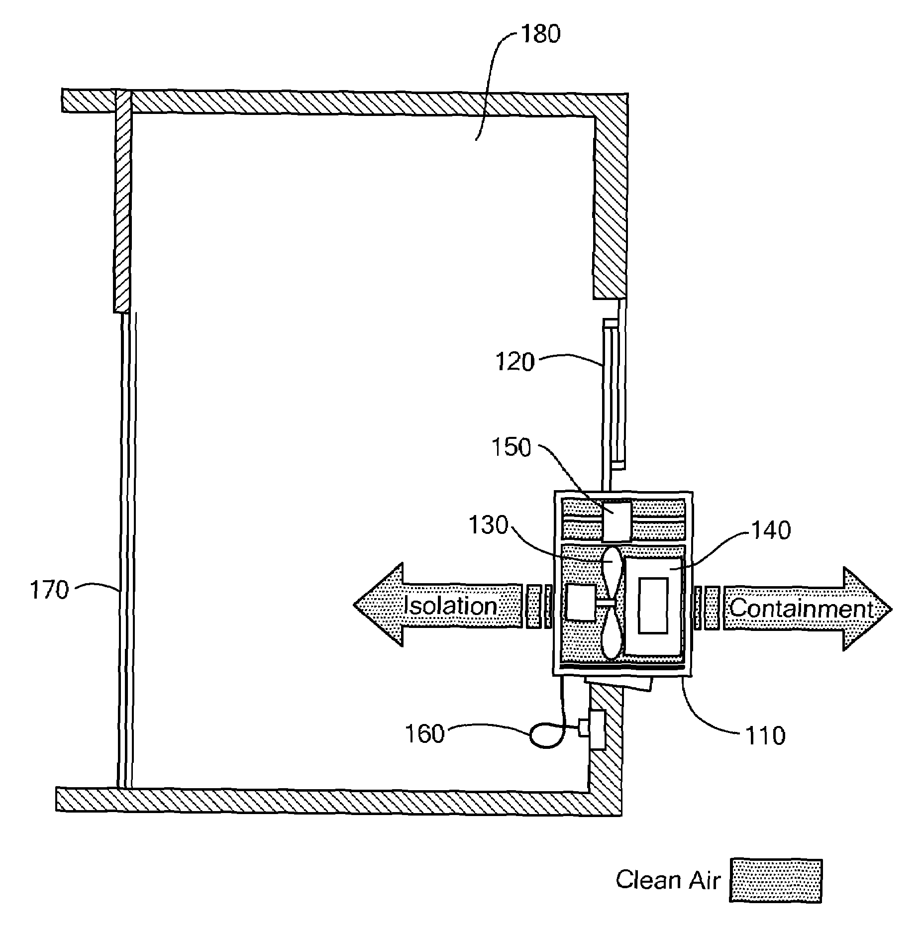
[0035]FIG. 1 shows an air-pressure-isolation system 110 in accordance with the present invention. The system 110 may be a through window, “plug and play” type system. As such, the system 110 can transform a closed space 180 into either an isolation or containment room by placing the system 110 into a window 120 and plugging a power cord 160 into a standard wall socket. The inward facing side of the system 110 may have a stylish design so that it does not negatively impact the aesthetics of the closed space 180. The outward facing side of the system 110 may have a design that it is suitable for exposure to the environment.

[0036]In an isolation configuration, a variable speed fan 130 forces clean air into the closed space 180, resulting in a positive pressure within the closed space 180. In order to produce a constant positive pressure consistent with surgical sites and clean rooms, the system 110 may control the air flow into the room, by varying the speed of the fan, to match the ai...


PUM

PropertyMeasurementUnit
wavelengthaaaaaaaaaa
pressureaaaaaaaaaa

Abstract

An air-pressure-control system, the system comprising a system inlet, a system outlet, and a variable-speed fan configured to operate at a speed. A motor controller in communication with the fan is configured to control the speed of the fan. A differential-pressure transducer configured to monitor an air pressure at the system inlet and an air pressure at the system outlet. A closed-loop pressure controller in communication with the motor controller and differential-pressure transducer, wherein the pressure controller is configured to vary the speed of the fan based on the pressure differential between the inlet and outlet of the system, thereby controlling a pressure within a space. An ultraviolet kill chamber may be disposed between the inlet and outlet to expose airborne particulate to UV radiation. The system may also have a filter located within an air-flow path between the system inlet and system outlet.

Description

PRIORITY[0001]This application claims priority to provisional application Ser. No. 60 / 802,977, filed May 24, 2006, entitled “Positive Air Pressure Isolation System,”, and naming David W. Palmer as inventor, the disclosure of which is hereby incorporated by reference in its entirety.FIELD OF THE INVENTION[0002]The invention generally relates to a positive air pressure isolation system. More specifically, the invention relates to the management and cleaning of air flow in or out of a closed space to produce a constant positive (+) or negative (−) room air pressure.BACKGROUND ART[0003]Air pressure control systems are used in many hospital room and semiconductor clean room applications to create isolation and containment areas. Isolation and containment techniques manage airborne micron size particles and micro organisms such as viruses, bacteria, fungus, mold, spores, and dust. Such techniques add to the health benefits of those living and working in the pressurized room by filling the...

Claims


Application Information

Patent Timeline
Patent Type & Authority Patents(United States)
IPC IPC(8): F24F11/00B01D39/00B01D50/00F24F8/108
CPCA61L9/20F24F3/166F24F11/0079B01L1/04F24F3/1603F24F11/001Y02B30/746F24F2003/1667F24F2011/0004F24F2011/0039F24F2011/0042F24F11/30F24F2110/00F24F2110/32F24F2110/40F24F11/77Y02B30/70F24F8/192F24F8/22Y02A50/20F24F11/64F24F8/108
Inventor PALMER, DAVID W.
Owner AMERICAN INNOVATIVE RES CORP
Why Eureka
Try Eureka