Flat eccentric rotor equipped with a fan and flat vibration motor equipped with a fan comprising same rotor
a technology of eccentric rotor and flat vibration motor, which is applied in the direction of positive displacement liquid engine, liquid fuel engine, piston pump, etc., can solve the problem that the space for installing the fan motor cannot be considered, and achieve the effect of increasing eccentricity, increasing vibration and air flow, and increasing the amount of vibration
- Summary
- Abstract
- Description
- Claims
- Application Information
AI Technical Summary
Benefits of technology
Problems solved by technology
Method used
Image
Examples
first embodiment
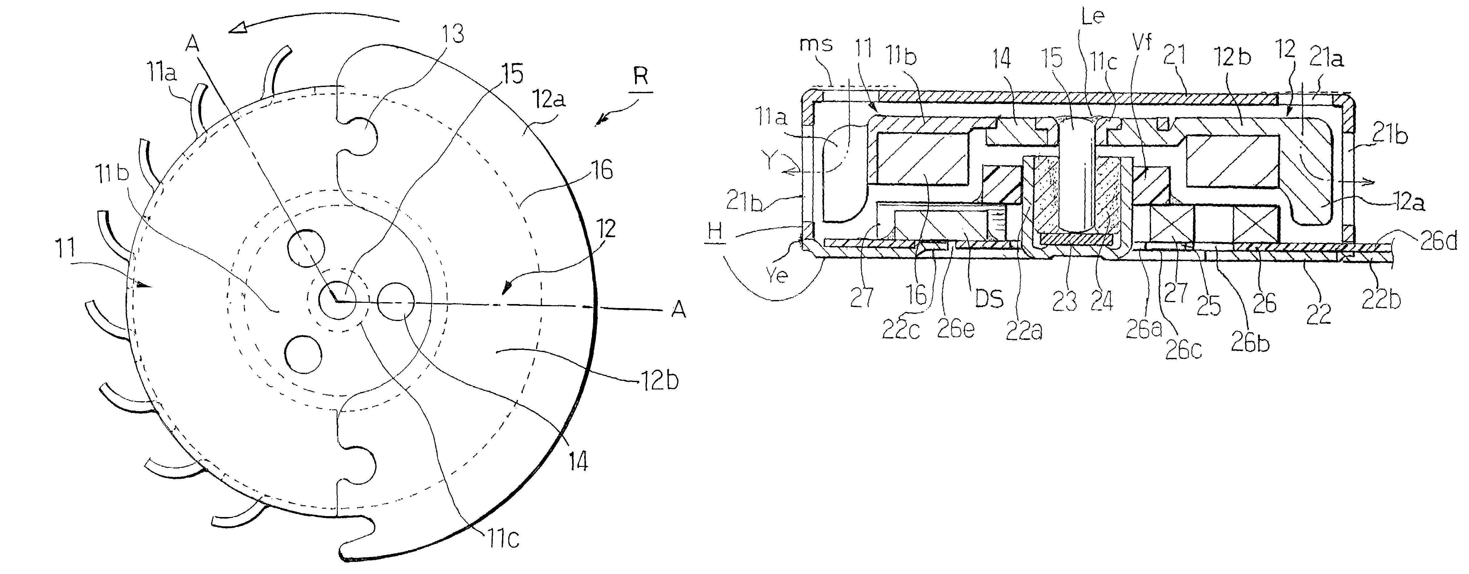
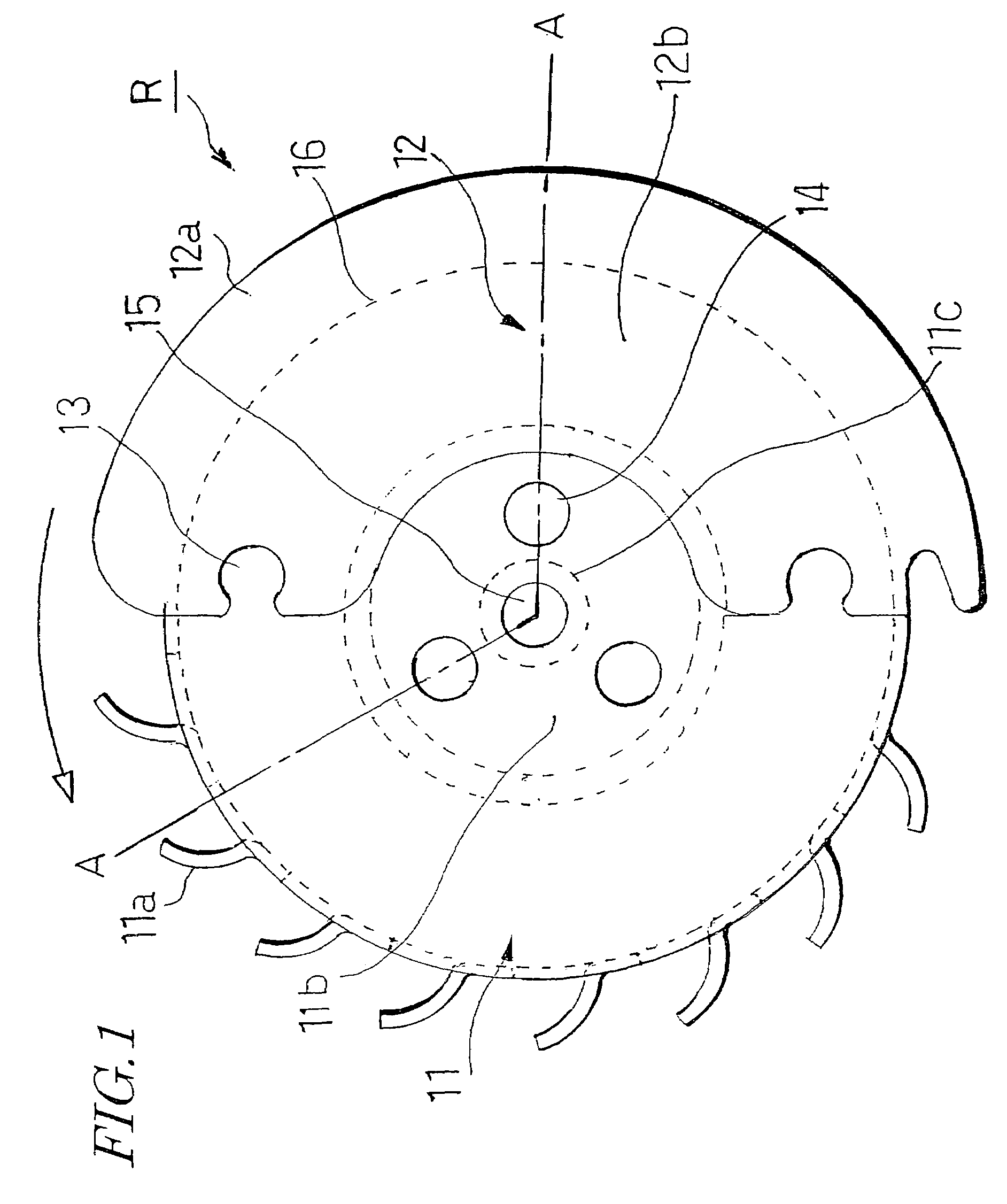
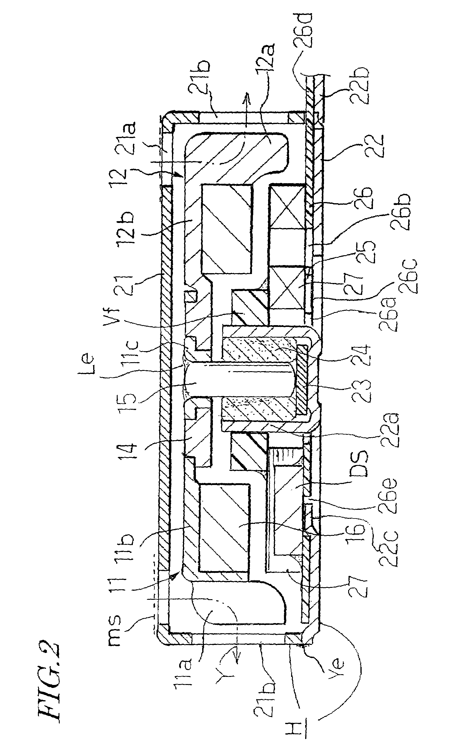
[0063]Referring to FIG. 1 and FIG. 2, the invention has an eccentric rotor R, a second fan part 11 with a low specific gravity that comprises a metal plate material with a specific gravity of 4 to about 9 and a first fan part 12 with a high specific gravity made from tungsten are assembled with a key-shaped concave-convex section 13 and a mating concave-convex section 14. In the second fan part 11 a plurality of backward vane-like impellers 11a are cut to be in a protruding condition on the outer periphery, and a shaft support section 11c of a shallow burr-like shape is provided in a center of rotation of a flat section 11b of the second fan part 11.
[0064]The first fan part 12 is disposed opposing the impellers 11a across a center of rotation and has convex and concave sections at ends thereof provided to the extent of a revolution circumference, or outermost rotational periphery, i.e., path, of the impellers 11a, and a circular-arc eccentric member 12a formed as an impeller in the ...
third embodiment
[0070]A stator base 26 which is assembled with the detent torque generating member 25 is made from a glass cloth—epoxy resin substrate with a thickness of about 0.15 mm, and a through hole 26a arranged around a center of the detent torque generating member 25, guide holes 26b for hollow armature coil mounting formed with a pitch of 90° outwardly in the radial direction thereof, and three groove holes 26c passing in the radial direction from the through hole 26a are formed with an arrangement opening angle of 90° in the center, as shown in FIG. 5 illustrating a stator described below.
[0071]The position of the groove hole 26c is determined by the number of poles of the axial-gap magnet 16 of the assembled rotor. Here, when the number of poles of the magnet is four (opening angle of the magnetic poles is 90°), the position of the groove hole is about 22.5° from the center of each guide hole 26b for hollow armature coil mounting, which is the center of the hollow armature coil, that ha...
second embodiment
[0084]FIG. 3 and FIG. 4 illustrate a modification example of a flat eccentric rotor equipped with a fan of a In this example, a thin magnetic sheet 31a is disposed on the upper surface of the axial-gap magnet 16 as a fan part 31 with a low specific gravity, a shaft support section 31b is provided at the magnetic sheet 31a, and at least the impeller 31c is formed from a resin Js with a specific gravity of 2 or less integrally with the magnetic sheet 31a. A portion cut and raised on an outer periphery of the magnetic sheet 31a is included in the impeller 31c to serve as a frame 31d, and a total of three through holes 31e through which the resin Js passes are opened in the impeller 31c. The magnetic sheet 31a is thereby strongly integrated with the resin Js, and because of the frame 31d, the impeller 31c can be sufficiently functional, without being damaged despite a low specific gravity of the resin Js.
[0085]An eccentric weight 32 made from tungsten and having three backward vane-typ...
PUM
 Abstract
Description
Claims
Application Information
 - R&D
- Intellectual Property
- Life Sciences
- Materials
- Tech Scout
- Unparalleled Data Quality
- Higher Quality Content
- 60% Fewer Hallucinations
Browse by: Latest US Patents, China's latest patents, Technical Efficacy Thesaurus, Application Domain, Technology Topic, Popular Technical Reports.
© 2025 PatSnap. All rights reserved.Legal|Privacy policy|Modern Slavery Act Transparency Statement|Sitemap|About US| Contact US: help@patsnap.com


