
Microwave generator with variable frequency emission

a generator and variable frequency technology, applied in the direction of oscillator generators, pulse generators, pulse techniques, etc., can solve the problems of affecting the efficiency of the generator, the interference of the input side, and the matched electronic circuit with physical structure, so as to achieve the effect of reducing the interference and facilitating the matched

Inactive Publication Date: 2009-12-01
DIEHL BGT DEFENCE GMBH & CO KG
View PDF8 Cites 36 Cited by
  • Summary
  • Abstract
  • Description
  • Claims
  • Application Information

AI Technical Summary

Benefits of technology

"The invention is about a microwave generator that uses reflectors to improve the pulse response and frequency spectrum. The resonant frequency of the reflectors should match that of the generator resonator. The dimensions of the reflectors transversely with respect to the generator longitudinal axis do not significantly affect the pulse behavior, so a telescopic rod with a short length can be easily matched to the generator length. The mutual separation between the tuned reflectors has a major influence on the emitted spectrum, so the operation between the reflectors leads to amplification of the energy to be emitted and thus of the external effect. The microwave generator can be trimmed easily to the desired frequency emission by adjusting the coupling piece between the resonator and the funnel antenna."

Problems solved by technology

The discharge-current pulse with a typical duration of only a few nanoseconds leads to broadband emission of a microwave spectrum in the range from about 200 to 400 MHz, with such a high energy density that radio links that are formed in the relatively close vicinity can at least be adversely affected, and electronic circuits with physical structures matched to the resonance condition may in particular be subject to interference on the input side, or may even be destroyed.
The spindle guide described there for axial movement of a short-circuiting link for adjustment of the length of the discharge current path admittedly allows continuous variation of the median frequency in the emitted spectrum, but requires a comparatively large and largely unused physical space, and is also mechanically quite complex.

Method used


Image

  • Microwave generator with variable frequency emission
  • Microwave generator with variable frequency emission

Examples


Embodiment Construction

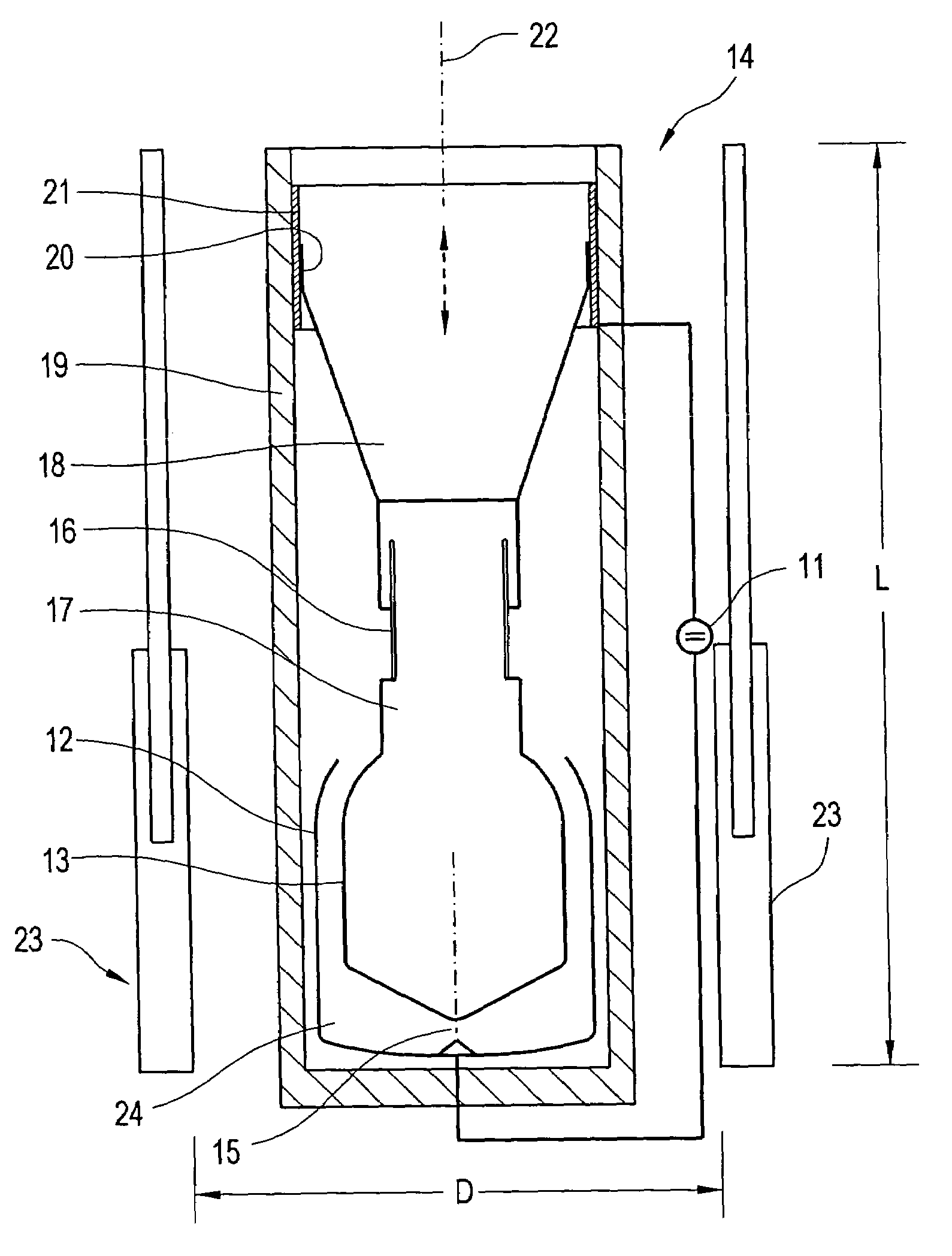
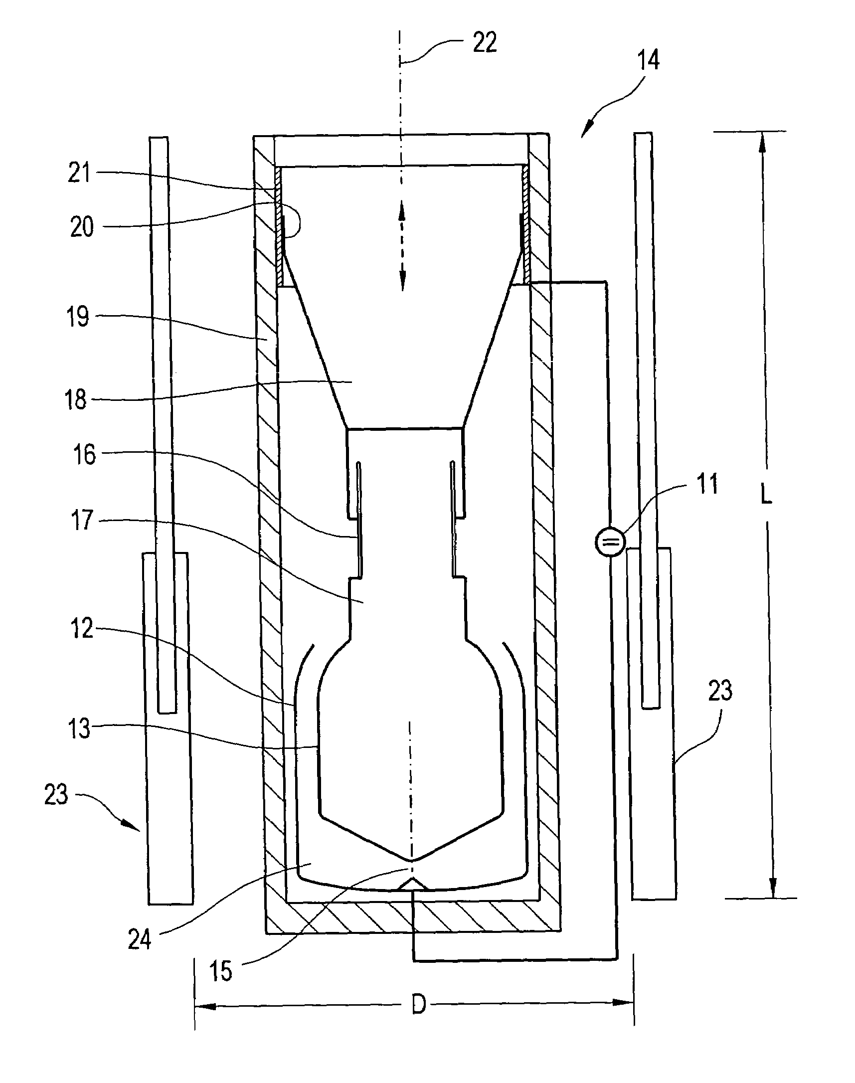
[0012]The capacitance, which is charged from a high-voltage DC generator 11, between the tubular outer electrode 12 and the inner electrode 13, which is in the form of a bottle, of the coaxially formed microwave generator 14 is discharged at the free end of the inner electrode 13 via a spark gap 15, whose short-circuiting results in the behaviour of a quarter-wave resonator 24. This discharge leads to a rapidly rising and highly oscillating discharge current as well via a coupling piece 16 between the bottle neck 17 and the antenna 18, which widens in the form of a funnel, in the tubular surrounding housing 19. The bandwidth of the emission and the pulse length of the discharge current are governed primarily by the axial length of this conical antenna 18. The median frequency in the emitted spectrum is governed primarily by the length of the coaxial resonator 24 in the form of the concentric electrode pair 12-13, although the length dimensions of the bottle neck 17, of the coupling ...


PUM


Abstract

The median frequency in the emission from a microwave generator (14), which operates in a pulsed manner, is shifted when the generator (14) operates between passive reflectors (23) whose axes are parallel thereto. In the axial direction, the reflectors (23) are approximately the same length (L) as the generator (14), with length matching through telescopic rods being preferable. However, the frequency is governed primarily by the distance (D) between the reflectors (23-23) between which the generator (14) is operated. Once desired resonance conditions have been found, for example for injection of microwave radiation into the mechanical structure of an external arrangement, this frequency relationship can be fixed by the magnitude of the length of the preferably telescopic coupling piece (16) between the resonator (13) and the antenna (18).

Description

BACKGROUND OF THE INVENTION[0001]1. Field of the Invention[0002]The invention relates to a variable-frequency microwave generator with a coaxial arrangement of a capacitive resonator and antenna for, in each case, a brief emission of a high-energy spectrum of damped sinusoidal oscillations during the discharge of the capacitor between the outer and inner electrodes of the resonator.[0003]2. Discussion of the Prior Art[0004]A generator of the above-mentioned type is described in DE 1 01 51 565 B4 as a mechanically tuneable resonant system, applied to a microwave generator of the type, which is explained functionally and in design terms in more detail in DE 1 03 13 286 B3 with reference to DE 1 01 51 565 B4. According to these documents, the capacitance, which is charged to a high voltage, between an inner electrode, which is in the form of a bottle, and a hollow-cylindrical outer electrode, which coaxially surrounds it, in an electromechanical resonator is discharged via a spark gap ...

Claims


Application Information

Patent Timeline
Patent Type & Authority Patents(United States)
IPC IPC(8): H03B7/12
CPCH03B11/00H01T9/00
Inventor STAINES, GEOFFREY
Owner DIEHL BGT DEFENCE GMBH & CO KG
Learn More