
Computer aided treatment planning

a computer and treatment planning technology, applied in the field of surgical planning, can solve the problems of limited spatial relationship between 2d ct and important structures, difficult examination of ear, severe conductive hearing loss, etc., and achieve the effect of high degree of risk

Inactive Publication Date: 2009-12-08
THE RES FOUND OF STATE UNIV OF NEW YORK
View PDF66 Cites 66 Cited by
  • Summary
  • Abstract
  • Description
  • Claims
  • Application Information

AI Technical Summary

Benefits of technology

[0015]The manipulation of the 3D image can be costly and processor intense. Preferably, the step of generating the 3D image of a region includes acquiring a set of 2D images of a region; applying segmentation to extract structures of interest; converting the 2D images to a voxel based dataset of region; storing the voxel based dataset in a partitioned data structure; and rendering the 3D image from the voxel based dataset. The partitioned data structure can take the form of a binary space partitioning (BSP) tree having a number of leaf nodes where the voxels of the voxel based dataset are stored. Using this form of data structure, the step of applying the intervention can preferably include: identifying those leaf nodes which are effected by the intervention; applying the intervention to the effected leaf nodes to launch voxel based constructive solid geometry (CSG) operation and image regeneration; and re-rendering only the portions of the 3D image associated with the effected leaf nodes. In this way, the aforementioned processing burden can be reduced. In addition, voxel-based constructive solid geometry (CSG) subtraction and level-of-detail rendering can also be used to reduce the processing burden.
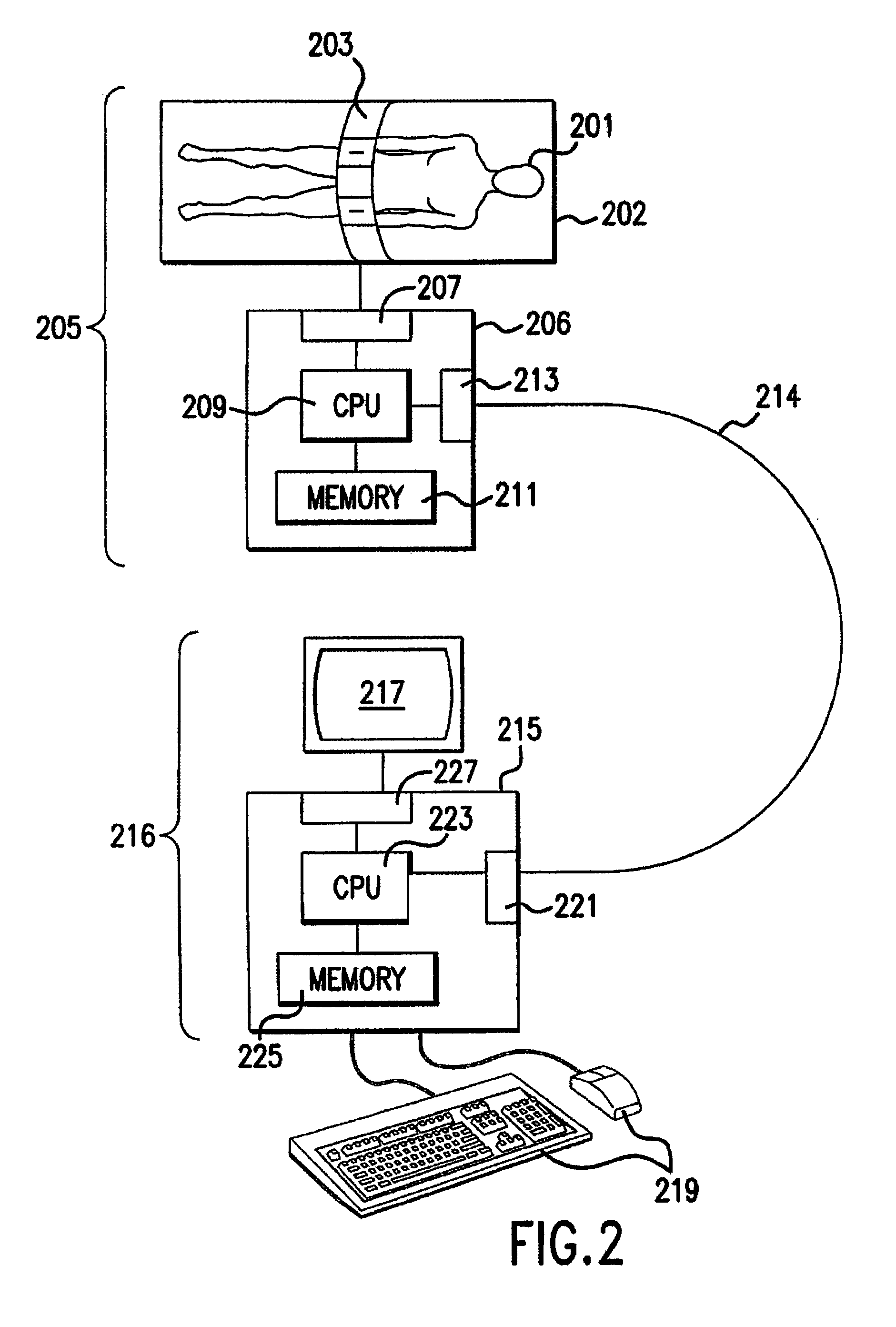
[0022]A system for computer aided treatment planning includes a scanner, such as a CT or MRI scanner, for acquiring image data from a patient. A processor is provided which receives the image data and generates a 3D, voxel based dataset representing at least a portion of the image data. A display, such as a liquid crystal display (LCD) or Cathode Ray Tube (CRT) is operatively coupled to the processor and provides a 3D representation the image data from the voxel based dataset. A user interface device, such as a mouse or trackball, is operatively coupled to the processor and allows a user to manipulate the image on the display. Computer readable memory is operatively coupled to the processor and has a computer program stored therein. The computer program directs the processor to perform the steps of: applying a virtual intervention in the region of the 3D image in response to a signal from the user interface device; analyzing the intervention and automatically generating a warning indication if the intervention results in a high degree of risk arising. Previewing a contemplated treatment virtually, through the user interface, the user can modify the intervention to eliminate the warning.

Problems solved by technology

The ear is an internal organ that is difficult to examine because it is encased in the temporal bone.
This disease results in conductive hearing loss which can be severe.
However, because of the complex anatomy of the ear and the risks associated with this surgical procedure, such as facial paralysis, thorough surgical planning is required to assess and maximize the likelihood of successful surgery.
However, the 2D CT is limited in its ability to represent the spatial relationships between these important structures.
For example, an aberrant facial nerve, a retro-displaced temporamandibular joint, or a low-lying tegmen tympani might make surgical reconstruction difficult or impossible.

Method used


Image

  • Computer aided treatment planning
  • Computer aided treatment planning
  • Computer aided treatment planning

Examples


Embodiment Construction

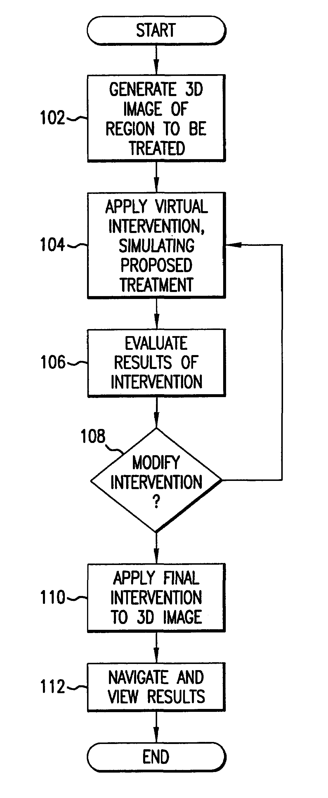
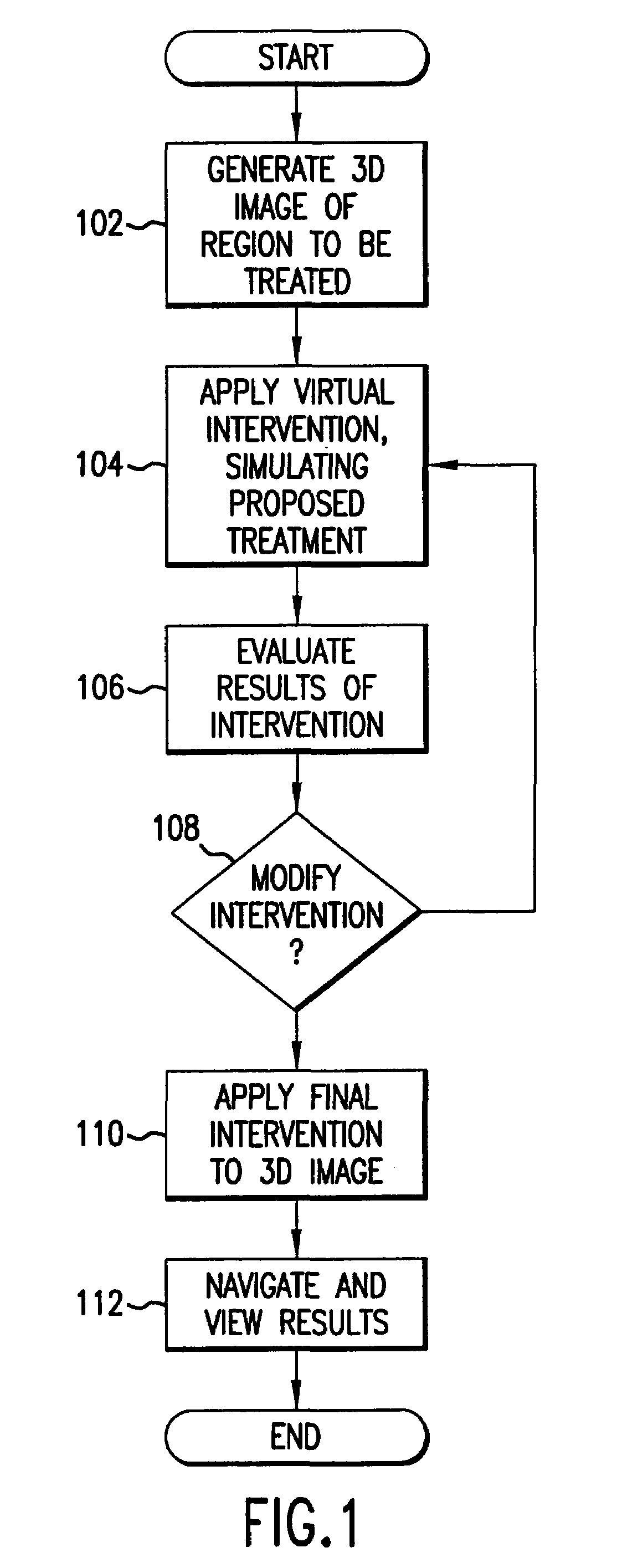
[0037]FIG. 1 is a flow chart which illustrates an overview of the present method of computer aided treatment planning which is generally performed on a computer based system, such as that illustrated in FIG. 2. The invention will be described in terms of medical applications performed on human patients and in the context of medical treatment, such as surgery, prosthesis implantation, biopsy, medication, therapeutic radiation, therapeutic ultrasound and the like. It will be appreciated, however, that the invention is not limited to human patients, nor to the exemplary list of treatments referenced. The term treatment is used to mean an intervention in a region, such as but not limited to tissue, that is intended to effect an alteration of the region.

[0038]Referring to FIG. 1, the method includes the initial step of generating a three dimensional (3D) image representation of a region for which some form of medical treatment or intervention is contemplated (step 102). Generating such a...


PUM


Abstract

A method of computer aided treatment planning is performed by generating and manipulating a three dimensional (3D) image of a region which includes at least one anatomical structure for which treatment, such as surgery, biopsy, tissue component analysis, prosthesis implantation, radiation, chemotherapy and the like, is contemplated. A virtual intervention, which simulates at least a portion of the contemplated treatment, is performed in the 3D image. The user can then determine the effect of the intervention and interactively modify the intervention for improved treatment results. Preferably, a warning is automatically provided if the intervention poses a risk of detrimental effect. The user can navigate through the contemplated region in the 3D image and assess the results. The treatment plans can be saved for comparison and post treatment evaluation.

Description

STATEMENT OF GOVERNMENT RIGHTS[0001]This invention was made with government support under grant number CA 079180 awarded by the National Institutes of Health. The government has certain rights in the invention.FIELD OF THE INVENTION[0002]The present invention relates generally to surgical planning and more particularly relates to a system and method of using three dimensional interactive computer visualization in surgical planning, optimization and evaluation.BACKGROUND OF THE INVENTION[0003]In many areas of medical treatment, it would be beneficial for a medical practitioner to be able to visualize a region for which treatment is contemplated and to accurately simulate the contemplated treatment. By visualizing the effect of the simulated treatment and altering the proposed treatment to optimize the results in a virtual setting, results can be improved and risks associated with the actual treatment can be reduced. This is particularly true in the case of invasive procedures such as...

Claims


Application Information

Patent Timeline
IPC IPC(8): A61B5/05A61B19/00G06F19/00G06T15/00G06T17/40
CPCA61B19/52G06F19/3437G06T15/08G06T19/003G06F19/3481A61B19/50G06F19/321Y10S128/922G06T2210/41A61B90/36A61B34/10G16H50/50G16H30/20G16H30/40G16H50/20
Inventor LIANG, ZHENGRONGLI, BINCHEN, DONGQINGSMOUHA, ERIC E.ROQUE, CLEMENTE T.KAUFMAN, ARIE E.WAX, MARK R.KREEGER, KEVIN
Owner THE RES FOUND OF STATE UNIV OF NEW YORK
Learn More