Exhaust gas purification control of diesel engine

a technology for exhaust gas purification and diesel engines, applied in the direction of electric control, machines/engines, separation processes, etc., can solve the problems of reducing the capacity of the nox trap catalyst, inconvenient operation, and large amount of particulate matter in the dpf, so as to prevent too much increase in the amount of dpf deposition of particulate matter, the effect of increasing the exhaust resistan

Inactive Publication Date: 2009-12-15
NISSAN MOTOR CO LTD
View PDF8 Cites 96 Cited by
  • Summary
  • Abstract
  • Description
  • Claims
  • Application Information

AI Technical Summary

Benefits of technology

[0010]It is therefore an object of this invention to follow and prevent too much increase in the particulate matter deposition amount of the DPF by integrative control of regeneration of the DPF and operation of the NOx trap catalyst.
[0012]This invention also provides an exhaust gas purification method for a diesel engine, wherein the engine comprises a diesel particulate filter which traps particulate matter contained in an exhaust gas of the diesel engine, and a device which adjusts an oxygen concentration of the exhaust gas flowing into the diesel particulate filter. The method comprises calculating a particulate matter deposition amount in the diesel particulate filter, and controlling the adjusting device, when the particulate matter deposition amount exceeds a first predetermined amount, so that the oxygen concentration of the exhaust gas does not become a value corresponding to a rich air-fuel ratio.

Problems solved by technology

SOx deposited on the NOx trap catalyst reduces the NOx trap capability of the NOx trap catalyst.
If two or more of these operations overlap, the following incoveniences may occur.
When regeneration of the DPF is not possible, or when regeneration of the DPF stops before complete regeneration of the DPF after regeneration has started, a large amount of particulate matter may remain in the DPF.
As a result, if the deposition amount exceeds the trap limit, it not only may lead to an increase of exhaust resistance, but it may also make vehicle running difficult.

Method used


Image

  • Exhaust gas purification control of diesel engine
  • Exhaust gas purification control of diesel engine
  • Exhaust gas purification control of diesel engine

Examples


Embodiment Construction

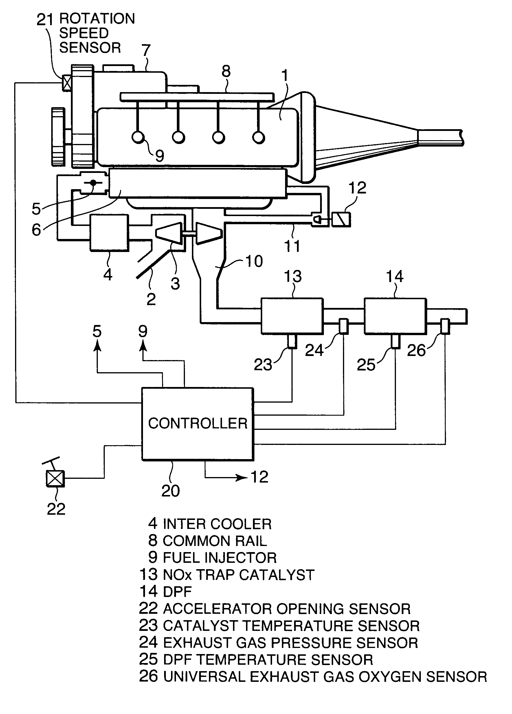
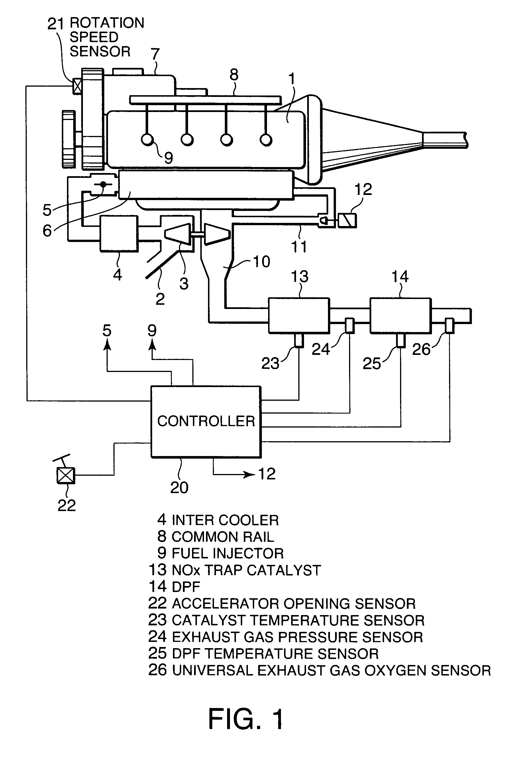
[0025]Referring to FIG. 1 of the drawings, a diesel engine 1 for a vehicle is provided with an intake passage 2 and exhaust passage 10. An intake compressor of a variable nozzle turbocharger 3 is disposed in the intake passage 2. In the exhaust passage 10, an exhaust turbine of the variable nozzle turbocharger 3 is provided. The variable nozzle turbocharger 3 rotates the exhaust turbine by the exhaust pressure of the exhaust passage 10, rotates the intake compressor on the same shaft, and supercharges the intake air of the intake passage 3. The intake air is cooled by an intercooler 4, and the supercharged intake air is aspirated into the combustion chamber of each cylinder via an intake throttle 5 and collector 6.

[0026]The diesel engine 1 also supplies fuel to each cylinder by a common rail type fuel supply system. The fuel supply system is provided with a high pressure fuel supply pump 7 which pressurizes fuel, a common rail 8 which stores the pressurized fuel, and a fuel injector...


PUM

PropertyMeasurementUnit
temperatureaaaaaaaaaa
temperature T22aaaaaaaaaa
temperatureaaaaaaaaaa

Abstract

A diesel particulate filter (14) which traps particulate matter and a NOx trap catalyst (13) which traps nitrogen oxides are installed in series in an exhaust passage (10) of a diesel engine (1). A controller (21) calculates a particulate matter deposition amount in the diesel particulate filter (14) (S4). The controller (21), when the particulate matter deposition amount exceeds a first predetermined amount (PM2), prevents sharp increase of the particulate matter deposition amount by prohibiting rich spike where the oxygen concentration of the exhaust gas is controlled to a value corresponding to a rich air-fuel ratio in order to regenerate the NOx trap catalyst (13) (S301, S302, S306), and prevents the particulate matter deposition amount of the diesel particulate filter (14) from reaching a limit.

Description

FIELD OF THE INVENTION[0001]This invention relates to exhaust gas purification control of a diesel engine.BACKGROUND OF THE INVENTION[0002]A diesel particulate filter (DPF) which traps particulate matter in the exhaust gas of a diesel engine for vehicles has a particulate matter deposition limit, and when the deposition amount exceeds the limit, it becomes impossible to trap more particulate matter. Therefore, when the deposition amount reaches a predetermined level, a regeneration operation is performed to raise the temperature of the DPF, burn and remove the trapped particulate matter, and enable the DPF to trap particulate matter again.[0003]When the vehicle is running at low speed, the exhaust gas temperature is suppressed low. Since, in the case of a regenerative device which raises the temperature of the DPF by increasing the exhaust gas temperature, regeneration of the DPF cannot be performed when the vehicle is running at low speed, and as a result, a large amount of particu...

Claims


Application Information

Patent Timeline
Patent Type & Authority Patents(United States)
IPC IPC(8): F01N3/00
CPCF01N3/0821F01N3/0842F01N3/0871F02D41/029F01N9/002Y02T10/24F01N2900/1612Y02T10/47Y02T10/12Y02T10/40
Inventor SHIRAKAWA, TAKASHIISHIBASHI, YASUTAKATODOROKI, HIKARI
Owner NISSAN MOTOR CO LTD
Why Eureka
Try Eureka