
Devices, systems and methods for delivery of a fluid into a patient during a magnetic resonance procedure

a technology of magnetic resonance and fluid injection, which is applied in the field of devices, systems and methods for delivering fluid into patients during magnetic resonance procedures, can solve the problems of limited use, limited use of powered injectors, and relatively high cost of mri procedures, and achieves the effects of easy fabrication, minimal time required for setting up of the device of the present invention, and convenient patient wearability

Inactive Publication Date: 2009-12-15
BAYER HEALTHCARE LLC
View PDF37 Cites 63 Cited by
  • Summary
  • Abstract
  • Description
  • Claims
  • Application Information

AI Technical Summary

Benefits of technology

[0012]In one embodiment, the container, the pressurizing mechanism, the actuator and the flow regulator are MR compatible, thereby making the device suitable for use in or near the bore of an MR scanner.
[0017]Preferably, the container, the pressurizing mechanism, the actuator and the flow regulator are MR compatible, thereby making the device suitable for use in or near the bore of an MR scanner.
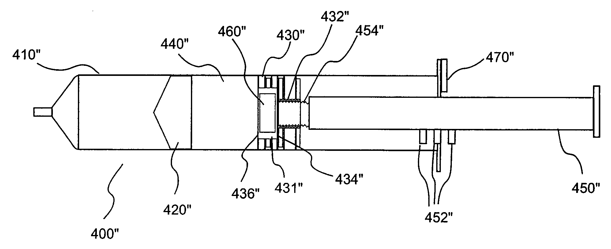
[0026]The injection device can further include a plunger extension operatively connected to the second plunger. In one embodiment, the injection device includes a stop mechanism to fix the position of the second plunger. The stop mechanism can, for example, include tabs on the plunger extension that abut with a stop member of the injection device to prevent movement of the injection device. In another embodiment, the plunger extension can be removable from connection with the second plunger and the injection device further includes a seal to close the rearward end of the syringe barrel after the plunger extension has been removed. It is not necessary, however, to seal the rearward end of the syringe barrel. As long as the second plunger is prevented from exiting the rear of the syringe, the injection device will be operable. Thus the injection device can alternatively include an abutment member that prevents the second plunger from exiting the rearward end of the syringe.
[0027]In a further embodiment, the plunger extension is axially movable relative to the second plunger to expel a material contained within a chamber of the plunger so that the material contacts a fluid in the intermediate volume with which the material reacts to generate a gas. The plunger can, for example, include threading, and the forward end of the plunger extension can include cooperating threading. In this embodiment, the plunger extension is rotated relative to the plunger to cause the plunger extension to move axially forward relative to the plunger. The axial forward motion of the plunger extension can, for example, force the material through a membrane separating the chamber of the plunger from the fluid within the intermediate volume. In one embodiment, rotation of the plunger extension also fixes the axial position of the second plunger within the syringe by bringing at least one contact member on the plunger into abutting engagement with at least one abutment member on the syringe.
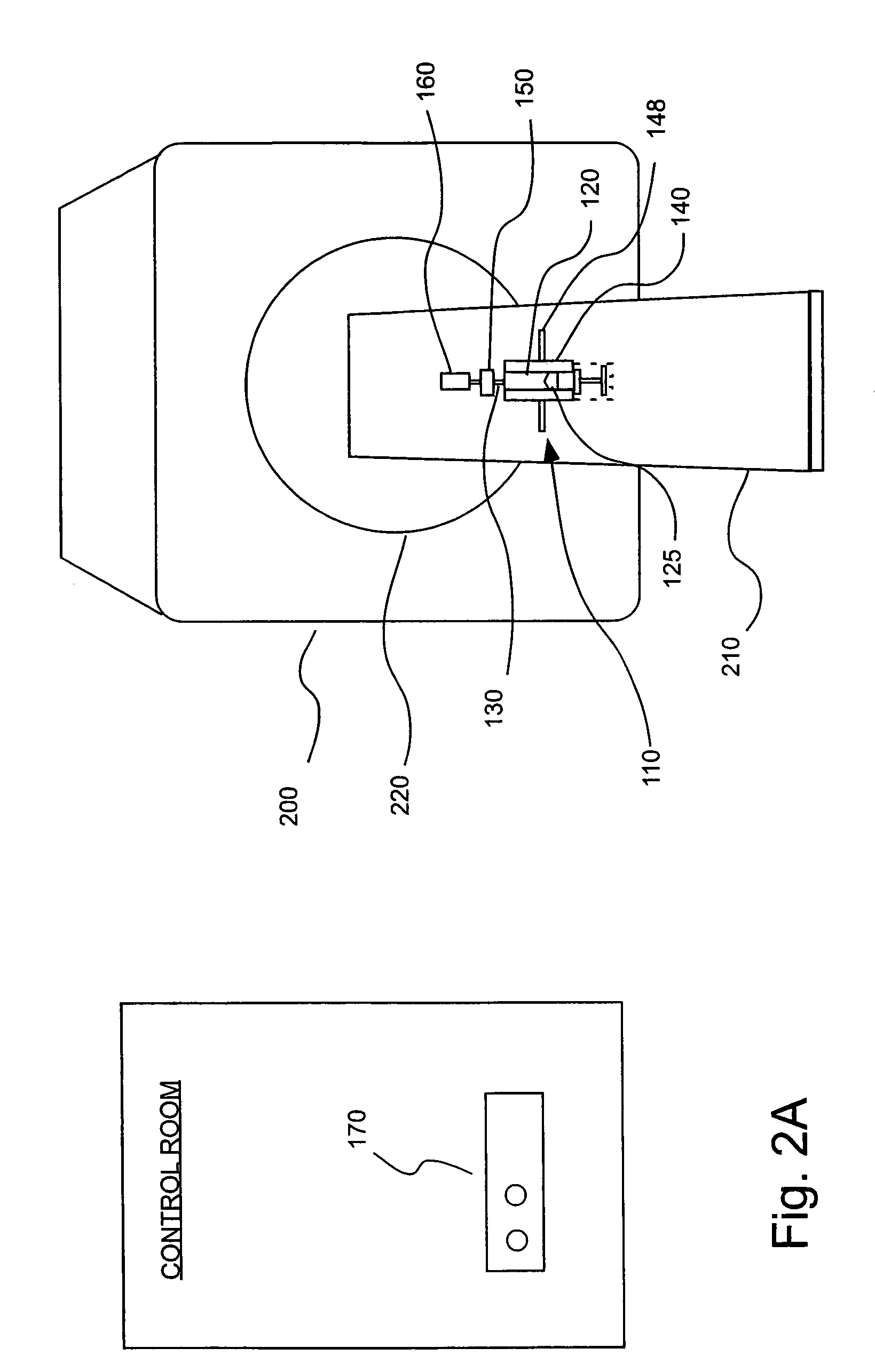
[0029]Numerous advantages are afforded by the injection devices of the present invention. For example, the devices are readily made patient wearable and readily fabricated to be fully in-bore compatible for MR procedures. The devices of the present invention can, for example, be applied to a patient outside the scanning room, and there is no need to remove a patient from the scanner bore to perform an injection. Likewise, the amount of time required for set up of the devices of the present invention is minimal. The devices of the present invention are also readily adaptable for remote activation, for example, from a scan control room. These advantages and others result in less time required for MR and other procedures and increase patient throughput.
[0030]Given the proximity of placement of the devices of the present invention to the patient, no saline flush to remove expensive contrast medium from the fluid path is required as is often necessary with current powered injectors in which long lengths of connective tubing are required. Indeed, in many embodiments of the present invention, less than three inches of connective tubing is required. Preferably, no more than one foot of connective tubing is required between the injection devices of the present invention and the injection point on the patient. The devices of the present invention are inexpensively and readily manufactured from relatively inexpensive materials and can be disposed of on a per-patient and / or other periodic basis, potentially reducing the risk of cross-contamination and making sterilization unnecessary.

Problems solved by technology

Although significant advances have been made in the design and operation of powered injectors, a number of problems persist which can limit their use.
However, powered injectors are used in only a relatively small percentage of such procedures.
In that regard, MRI procedures are relatively expensive and patient throughput is a primary concern.
It is perceived that use of powered injectors in such procedures will require additional time, while providing little benefit.
A number of problems often arise with the manual injection of contrast in an MRI procedure.
For example, after injection it is often difficult to reposition the patient in the same position in which the baseline measurement was made.
Even if repositioning can be achieved with success, removal of the patient from the bore to manually inject contrast and subsequent repositioning require a substantial amount of time.
Furthermore, it is sometimes difficult with some patients to properly inject the contrast manually.
In such cases, it may become necessary to call for the services of an IV specialist team, greatly increasing the amount of time required for the scan.
Even in imaging procedures other than MRI procedures (such as CT, angiography and ultrasound), there may be reluctance to use powered injectors in certain procedures because of perceived or actual burdens with such use.

Method used


Image

  • Devices, systems and methods for delivery of a fluid into a patient during a magnetic resonance procedure
  • Devices, systems and methods for delivery of a fluid into a patient during a magnetic resonance procedure
  • Devices, systems and methods for delivery of a fluid into a patient during a magnetic resonance procedure

Examples


Embodiment Construction

[0049]In general, the present invention provides infusion or injection devices and systems that are relatively easy to operate. The injection devices are preferably readily portable and can even be patient wearable.

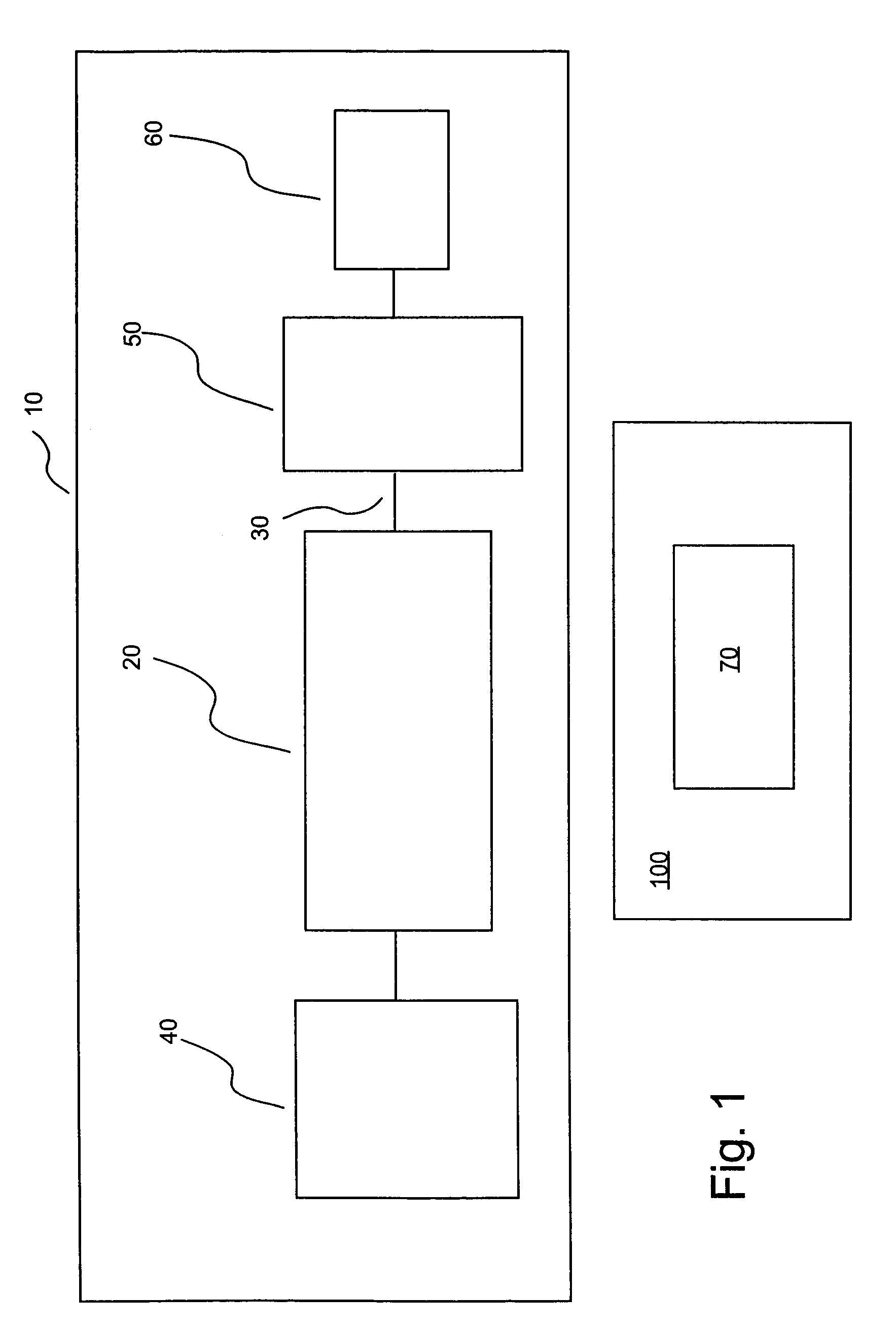
[0050]In the embodiment of the present invention illustrated in FIG. 1, an injection or infusion device 10 includes a storage container or chamber 20 (for example, a prefilled syringe) in which a fluid for injection into a patient is stored. Injection device 10 includes an outlet 30 in fluid connection with chamber 20 and through which fluid exits chamber 20 to be injected into the patient. Injection device 10 also includes a pressurizing mechanism 40 through which force / pressure is applied to the fluid within chamber 20 to cause the pressurized fluid to exit outlet 30. Injection device 10 further includes an actuator 50 to initiate (and, possibly, terminate) flow. Actuator 50 can, for example, be remotely operated via a controller from, for example, control room 100. Dev...


PUM


Abstract

A device for injection of a fluid into a patient includes a container adapted to hold the fluid and defining an outlet through which the fluid can exit the container. A pressurizing mechanism is in connection with the container for pressurizing the fluid, and an actuator is in fluid connection with the outlet. The actuator has a first state in which fluid is prevented from flowing through the outlet and a second state in which fluid can flow through the outlet. The injection device further includes a flow regulator to control the flow rate of fluid in fluid connection with the outlet. The container, the pressurizing mechanism, the actuator and the flow regulator can be MR compatible, thereby making the device suitable for use in or near the bore of an MR scanner.

Description

CROSS-REFERENCE TO RELATED APPLICATIONS[0001]This application claims the benefit of U.S. Provisional Application Ser. No. 60 / 495,972, filed on Aug. 18, 2003, the contents of which are incorporated herein by reference. This application is also related to U.S. application Ser. No. 10 / 916,946, filed on Aug. 12, 2004, titled “Actuators And Fluid Delivery Systems Using Such Actuators.”BACKGROUND OF THE INVENTION[0002]The present invention relates generally to devices, systems and methods for delivery of a fluid, and, particularly, for infusion or injection of a fluid into a patient.[0003]A number of injector-actuated syringes and powered injectors for use in medical procedures such as angiography, computed tomography (CT), ultrasound and NMR / MRI have been developed. U.S. Pat. No. 4,006,736, for example, discloses an injector and syringe for injecting fluid into the vascular system of a human being or an animal. Typically, such injectors comprise drive members such as pistons that connect...

Claims


Application Information

Patent Timeline
IPC IPC(8): A61M5/19
CPCA61M5/14526A61M5/007A61M2205/3362A61M2039/0009
Inventor COWAN, KEVIN P.TROMBLEY, III, FREDERICK W.REILLY, DAVID M.GRIFFITHS, DAVID M.MISIC, GEORGE J.CALLAN, KEITH
Owner BAYER HEALTHCARE LLC
Learn More