Distributed feed fuel cell stack

a fuel cell and stack technology, applied in the direction of cell components, fused electrolyte fuel cells, cell component details, etc., can solve the problems of poor thermal and fuel management, short life-span or even stack damage, and internal and external reforming suffer from large temperature variations within the stack, etc., to improve thermal management, improve thermal distribution, mass and thermal integration, and improve thermal management

a fuel cell and stack technology, applied in the direction of cell components, fused electrolyte fuel cells, cell component details, etc., can solve the problems of poor thermal and fuel management, short life-span or even stack damage, and internal and external reforming suffer from large temperature variations within the stack, etc., to improve thermal management, improve thermal distribution, mass and thermal integration, and improve thermal management

US7632596B2Inactive Publication Date: 2009-12-15ILLINOIS INSTITUTE OF TECHNOLOGY

Image

  • Distributed feed fuel cell stack
  • Distributed feed fuel cell stack
  • Distributed feed fuel cell stack

Examples


Embodiment Construction

Kinetics and Operation

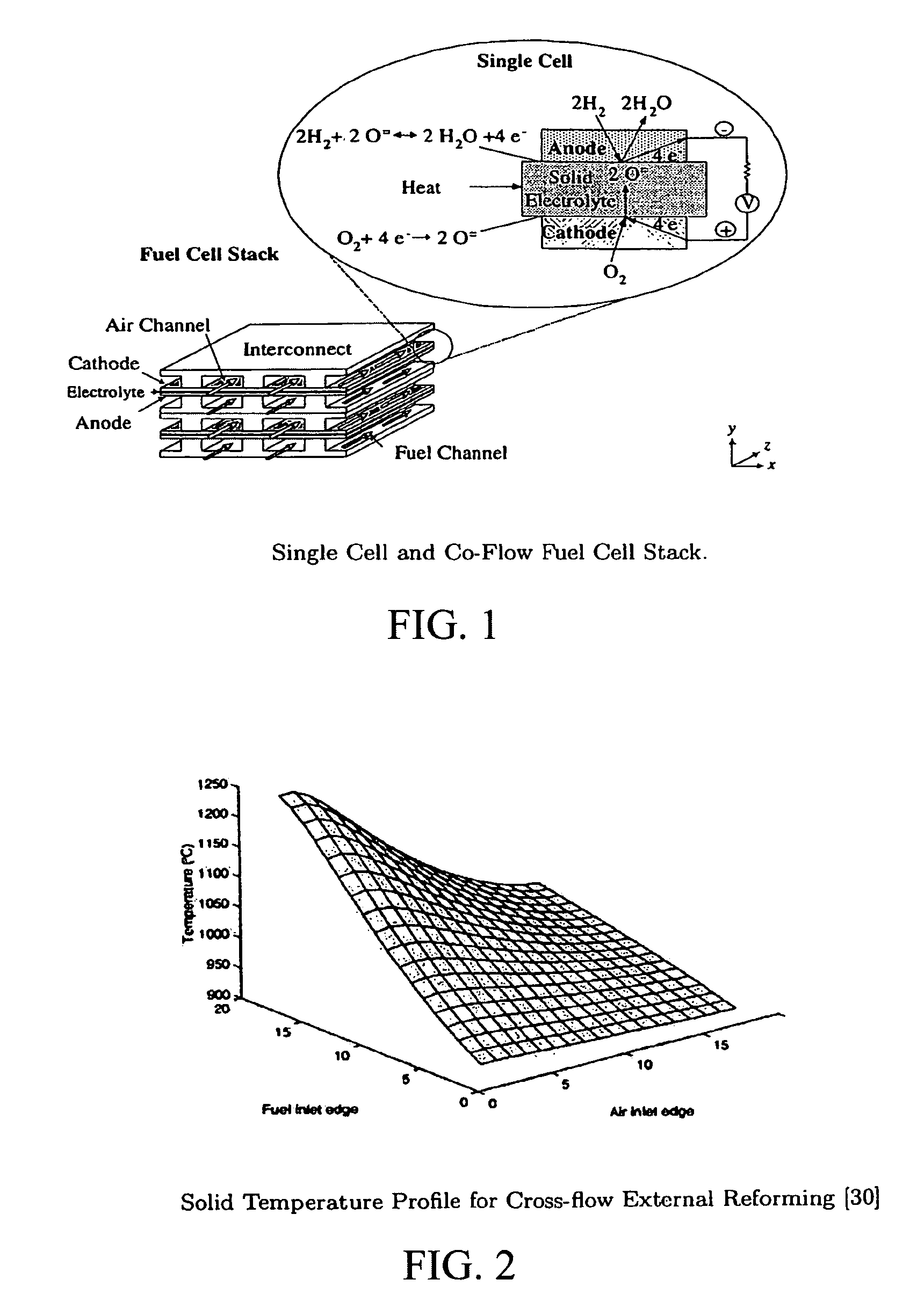
[0035]A fuel cell stack consists of four building blocks, which are anode, cathode, electrolyte and interconnect, as shown in FIG. 1. The oxidant, usually air, is fed on the cathode side to provide the needed oxygen for the electrochemical reaction. In addition, it serves as a coolant, when the fuel cell is hydrogen-fed. However, air provides the heat needed, when the fuel cell stack is methane-fed (i.e., internal reforming stack). The fuel is fed on the anode side. Oxygen ions are conducted by the electrolyte and electrons are conducted by the interconnect 2.1. Equations (2.1) and (2.2) are the anode hydrogen and the cathode electrochemical reactions respectively.

[0036]H2+O=⟶H2⁢O+2⁢⁢e-(2.1)12⁢O2+2⁢⁢e-⟶O=(2.2)

The sum of Equations (2.1) and (2.2) will lead to the cell overall reaction, which is shown below.

[0037]H2+12⁢⁢O2⟶H2⁢O(2.3)

As the reaction described by Equation (2.3) proceeds, a certain amount of energy is released (at 298K, ΔHrxn=242 kJ / mole). Unfortunat...


PUM

PropertyMeasurementUnit
temperatureaaaaaaaaaa
temperaturesaaaaaaaaaa

Abstract

A fuel cell having a distributed fuel feed in which the heat generation profile can be better controlled. Fuel channel stack and system efficiency improvements are achieved.

Description

[0001]This application claims priority from U.S. Provisional Application No. 60 / 517,463 filed 5 Nov. 2003.BACKGROUND OF THE INVENTIONDiscussion of the Related Art[0002]More than ever before, there is a strong need for a more efficient energy conversion device and a low emission power generation system. This demand is a result of strict emission rules and regulations, and the need to slow down the growing demand for fossil fuel. Fuel cells make an excellent candidate because of their high efficiency and very low emissions, which can be described as electrochemical devices that convert chemical energy into electrical energy.[0003]High temperature fuel cells, which are solid oxide fuel cell (SOFC) and molten carbonate fuel cell (MCFC), operate from 650° C. to 1000° C. and can attain an overall net low system efficiency of more than 70%. The high operating temperatures allow for the exhaust temperature to be utilized in bottoming cycles and / or co-generation. In addition, the heat produc...

Claims


Application Information

Patent Timeline
15 Dec 2009
Publication
US7632596B2
IPC
H01M2/14; H01M8/04; H01M8/12; H01M8/14; H01M8/24
CPC
H01M8/0258; H01M8/04089; H01M8/0618; H01M8/0637; Y02E60/526; H01M2008/147; Y02E60/50; Y02E60/525
Inventors
AL-QATTAN, AYMAN M.; CHMIELEWSKI, DONALD J.