Catadioptric optical system for scatterometry

a scatterometry and optical system technology, applied in the field of optical systems, can solve the problems of inability to easily detect or quantify the errors of the lithographic apparatus from resist patterns, the inability to use off-line techniques, and the inability to use resist patterns in resist patterns, etc., to achieve wide spectral range, wide spectral range, and high numerical aperture

Active Publication Date: 2009-12-15
ASML HLDG NV
View PDF15 Cites 14 Cited by
  • Summary
  • Abstract
  • Description
  • Claims
  • Application Information

AI Technical Summary

Benefits of technology

[0014]According to one embodiment of the present invention, there is provided a catadioptric optical system having a high numerical aperture operates in a wide spectral range. The catadioptric optical system includes a correcting plate, a first reflective surface and a second reflective surface. The correcting plate conditions electromagnetic radiation to correct at least one aberration. The first reflective surface is positioned to reflect the electromagnetic radiation conditioned by the correcting plate. The second reflective surface is positioned to focus the electromagnetic radiation reflected by the first reflective surface onto a target portion of a substrate. The electromagnetic radiation reflected by the first reflective surface and focused by the second reflective surface is not refracted by a refractive element, thereby enabling the catadioptric optical system to operate in a broad spectral range.

Problems solved by technology

Second, the measurements may allow errors in the lithographic apparatus, e.g., illumination settings or exposure dose, to be detected and corrected for in subsequent exposures.
However, many errors in the lithographic apparatus cannot easily be detected or quantified from the patterns printed in resist.
Such off-line techniques take time, often a considerable amount, reducing production time and during which the end products of the apparatus will be of an unknown quality until the measurement results are made available.
As a result, spectra with more than one wavelength have to be time-multiplexed, which increases the total acquisition time taken to detect and process the spectra.

Method used


Image

  • Catadioptric optical system for scatterometry
  • Catadioptric optical system for scatterometry
  • Catadioptric optical system for scatterometry

Examples


Embodiment Construction

I. Introduction

[0029]The present invention provides a catadioptric optical system for scatterometry. In the specification, reference to “one embodiment”, “an embodiment”, “an example embodiment”, etc., indicates that the embodiment described may include a particular feature, structure, or characteristic, but every embodiment may not necessarily include the particular feature, structure, or characteristic. Moreover, such phrases are not necessarily referring to the same embodiment. Further, when a particular feature, structure, or characteristic is described in connection with an embodiment, it is submitted that it is within the knowledge of one skilled in the art to affect such feature, structure, or characteristic in connection with other embodiments whether or not explicitly described.

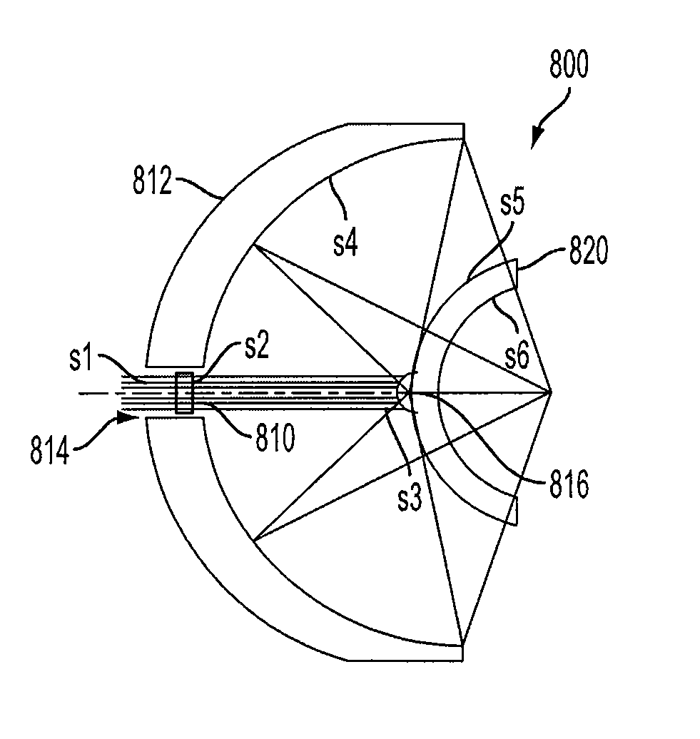
[0030]A catadioptric optical system in accordance with an embodiment of the present invention includes (i) a mirror system to provide a high numerical aperture and achromatism, and (ii) a nearly afoc...


PUM


Abstract

A catadioptric optical system having a high numerical aperture operates in a wide spectral range. The catadioptric optical system includes a correcting plate, a first reflective surface and a second reflective surface. The correcting plate conditions electromagnetic radiation to correct at least one aberration. The first reflective surface is positioned to reflect the electromagnetic radiation conditioned by the correcting plate. The second reflective surface is positioned to focus the electromagnetic radiation reflected by the first reflective surface onto a target portion of a substrate. The electromagnetic radiation reflected by the first reflective surface and focused by the second reflective surface is not refracted by a refractive element, thereby enabling the catadioptric optical system to operate in a broad spectral range.

Description

BACKGROUND[0001]1. Field of the Invention[0002]The present invention is generally directed to optical systems, and more particularly to catadioptric optical systems.[0003]2. Related Art[0004]A lithographic apparatus is a machine that applies a desired pattern onto a substrate or part of a substrate. A lithographic apparatus can be used, for example, in the manufacture of flat panel displays, integrated circuits (ICs) and other devices involving fine structures. In a conventional apparatus, a patterning device, which can be referred to as a mask or a reticle, can be used to generate a circuit pattern corresponding to an individual layer of an IC, flat panel display, or other device. This pattern can be transferred onto all or part of the substrate (e.g., a glass plate, a wafer, etc.), by imaging onto a layer of radiation-sensitive material (e.g., resist) provided on the substrate.[0005]The patterning device can be used to generate, for example, an IC pattern. The patterning device ca...

Claims


Application Information

Patent Timeline
Patent Type & Authority Patents(United States)
IPC IPC(8): G02B17/00G02B21/00G02B23/00G02B30/25
CPCG01N21/47G02B17/0808G02B17/0856G02B27/0025G03F7/70625G03F7/70633G01N2021/4714G02B21/04
Inventor SHMAREV, YEVGENIY KONSTANTINOVICHSMIRNOV, STANISLAV Y.POZHINSKAYA, IRINA I.
Owner ASML HLDG NV
Why Eureka
Try Eureka