
Transfer system

a transfer system and transfer technology, applied in the field of transfer systems, can solve the problems of insufficient achievement of the original object of link bundling, long maintenance time, and inability to control, so as to improve the maintenance and management efficiency of bundling transfer, improve the quality of transfer, and reduce the amount of route information

Inactive Publication Date: 2009-12-15
FUJITSU LTD
View PDF14 Cites 6 Cited by
  • Summary
  • Abstract
  • Description
  • Claims
  • Application Information

AI Technical Summary

Benefits of technology

The present invention provides a transfer system that improves transfer quality by reducing the amount of route information and the number of times advertisements are performed. The system includes a transmission-side transfer apparatus and a receiving-side transfer apparatus. The transmission-side transfer apparatus includes a path setting section and a transmission-side route-information advertisement section, while the receiving-side transfer apparatus includes a path recognition section and a receiving-side route-information advertisement section. The system reduces the amount of route information and advertisements, improves maintenance and management efficiency in bundling transfer, and enhances transfer quality.

Problems solved by technology

Since there are several hundreds to several hundred thousands links in total in the optical-fiber, wavelength, TDM, and IP layers in GMPLS, control cannot be made if each route information is advertised as in a conventional router.
This imposes a load on each node, which means that the original object of link bundling has not been sufficiently achieved.
Therefore, a human mistake may occur at setting operations, and maintenance needs a long time, generating a low efficiency in maintenance and management.
Furthermore, IETF does not explicitly determine whether a bundled link needs to be once released when a component link is added or deleted after the bundled link has been specified.

Method used


Image

  • Transfer system
  • Transfer system
  • Transfer system

Examples


Embodiment Construction

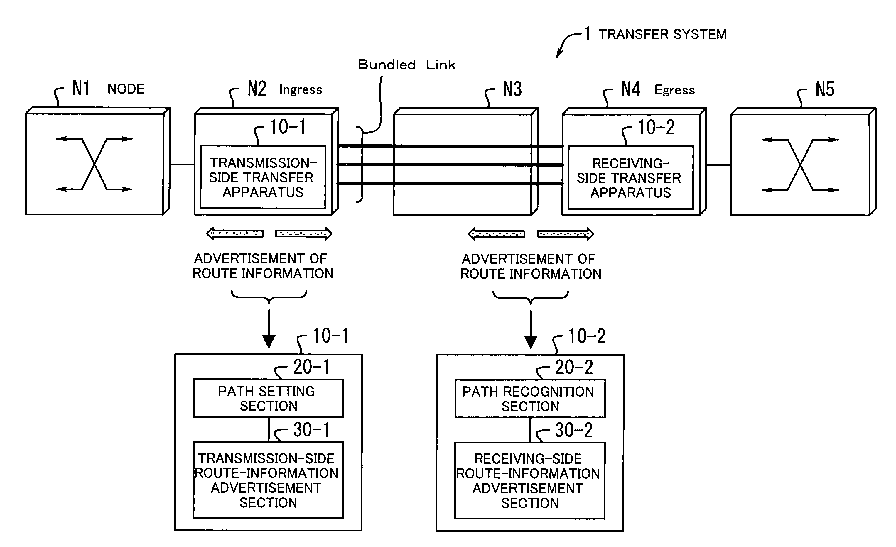
[0079]Embodiments of the present invention will be described below by referring to the drawings. FIG. 1 shows the concept of a transfer system 1 according to the present invention. The transfer system 1 includes a transmission-side transfer apparatus 10-1 and a receiving-side transfer apparatus 10-2, and applies transfer control to bundling which bundles a plurality of paths into one path.

[0080]In the figure, nodes N1 to N5 are connected in series. The node N2 serves as an inlet node (ingress) and has the transmission-side transfer apparatus 10-1. The node N4 serves as an outlet node (egress) and has the receiving-side transfer apparatus 10-2. A bundled link has been established between the node N2 and the node N4 via the node N3.

[0081]A bundled link refers to a single link which bundles paths having the same destination into one path. The functions of the transmission-side transfer apparatus 10-1 and the receiving-side transfer apparatus 10-2 according to the present invention are ...


PUM


Abstract

A transfer system for bundle transfer, in which the amount of route information and the number of times advertisement is performed are reduced, and maintenance and management are made to be highly efficient to implement improved transfer quality. A path setting section specifies a path between nodes for a receiving side as a bundled link which can have a plurality of paths tied up. A transmission-side route-information advertisement section advertises route information in a network when recognizing that the path has been established. A path recognition section recognizes the path and sets the path as a bundled link. A receiving-side route-information advertisement section advertises the route information in the network when recognizing that the path has been established.

Description

CROSS-REFERENCE TO RELATED APPLICATION[0001]This application is a continuing application, filed under 35 U.S.C. 111(a), of International Application PCT / JP2002 / 010305, filed on Oct. 2, 2002, the contents of which are herein wholly incorporated by reference.BACKGROUND OF THE INVENTION[0002]1. Field of the Invention[0003]The present invention relates to transfer systems, and particularly to a transfer system for applying transfer control to bundling which bundles a plurality of paths into one path.[0004]2. Description of the Related Art[0005]The amount of information handled in information communication networks has been exceedingly increased, and further advanced multimedia service is expected at a wider bandwidth. In such a situation, dense wavelength division multiplex (DWDM) has been developed as a high-traffic transfer technology.[0006]DWDM multiplexes light beams having different wavelengths at a high density to transfer a plurality of signals by one optical fiber at the same ti...

Claims


Application Information

Patent Timeline
Patent Type & Authority Patents(United States)
IPC IPC(8): H04L12/26H04J3/00H04L12/28H04L45/02H04L47/41H04Q11/00
CPCH04L45/00H04L45/50H04Q11/0062H04Q2011/0088H04Q11/0071H04Q2011/0073
Inventor KINOSHITA, HIROSHIPETERS, COLIN
Owner FUJITSU LTD
Learn More