
Series hybrid electric vehicle

a hybrid electric vehicle and electric vehicle technology, applied in the direction of electric devices, machines/engines, electric generator control, etc., can solve the problems of reducing energy efficiency, complicated drive train mechanism of parallel hybrid electric vehicles, and loss of energy, so as to improve the energy efficiency of series hybrid electric vehicles, avoid excessive increase of output voltage of rectifiers, and improve conversion efficiency

Inactive Publication Date: 2009-12-22
MITSUBISHI HEAVY IND LTD
View PDF73 Cites 45 Cited by
  • Summary
  • Abstract
  • Description
  • Claims
  • Application Information

AI Technical Summary

Benefits of technology

The present invention aims to improve the energy efficiency of a series hybrid electric vehicle by improving the efficiency of its electric generation system and drive system. This is achieved by using a rectifier to convert the alternating voltage generated by the n-phase generator into the direct voltage, which is then used to charge the battery. However, the use of the rectifier may cause an increase in the output voltage of the rectifier, which may cause deterioration of the battery. To address this issue, a switch is used to control the output voltage of the rectifier, based on the revolution speed of the engine. The use of multiple motors in the drive system eliminates the necessity of a transmission mechanism and a differential mechanism, improving efficiency. The motors used in the drive system are IPM motors, which are small in size and large in output torque. Overall, the invention improves the efficiency of the electric generation system and drive system, resulting in improved energy efficiency of the series hybrid electric vehicle.

Problems solved by technology

The drive train mechanism in the parallel hybrid electric vehicle is complicated, since both of the engine and the motor are mechanically connected to the drive wheels.
A complicated drive train mechanism may cause the loss of the energy.
The use of a mechanism that decreases the energy efficiency is not preferred, because it loses the advantage of the series hybrid electric vehicle.
It is difficult to avoid some loss, since the inverter is composed of switching transistors.
In the series hybrid electric vehicle where the high energy efficiency is requested, the losses of a transmission mechanism and a differential mechanism are also unignorable.

Method used


Image

  • Series hybrid electric vehicle
  • Series hybrid electric vehicle
  • Series hybrid electric vehicle

Examples


first embodiment

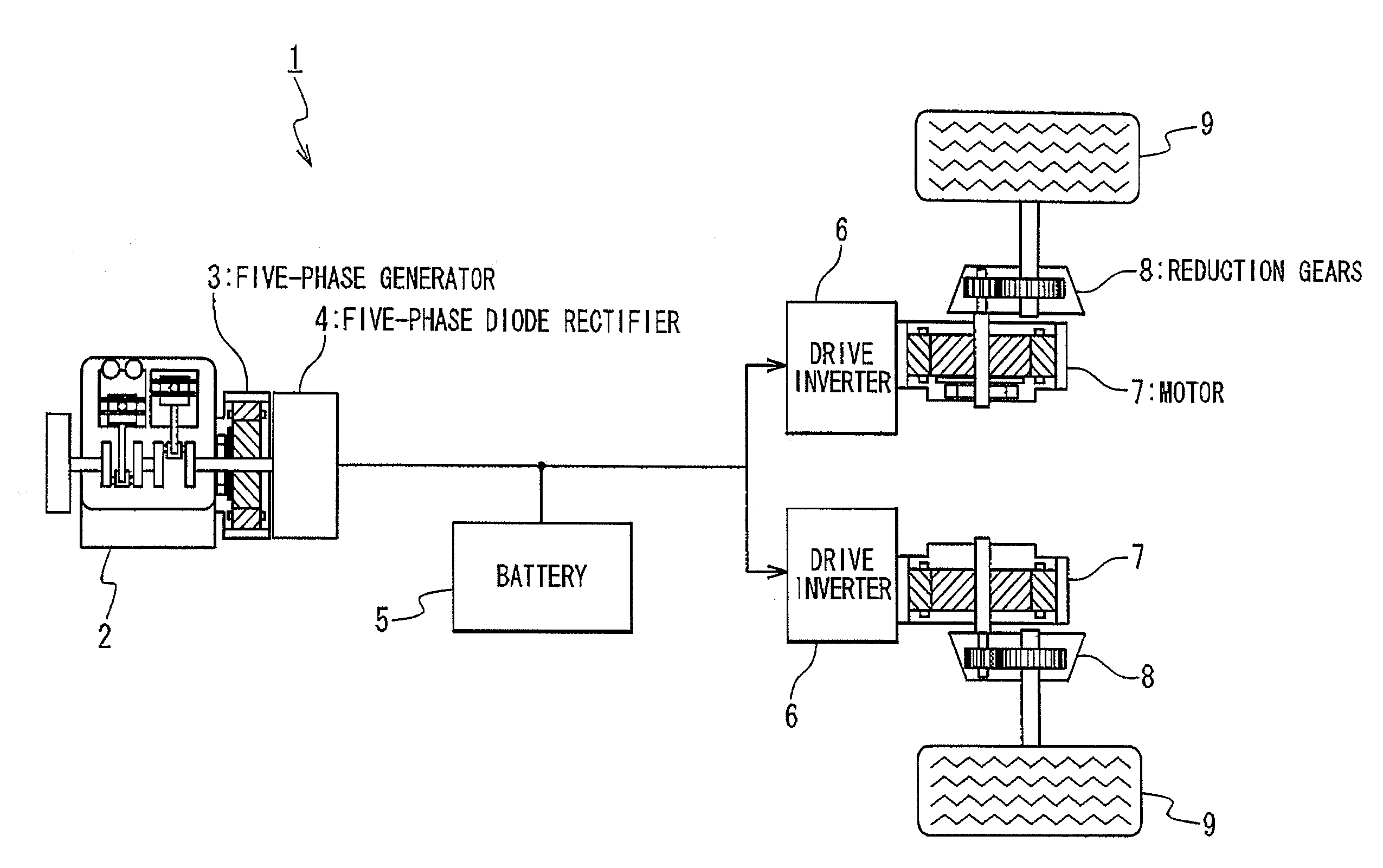
[0025]In a first embodiment of the present invention, as shown in FIG. 1, a series hybrid electric vehicle 1 is provided with an engine 2, a five-phase generator 3, a five-phase diode rectifier 4, and a battery 5. The revolution speed of the engine 2 is controlled by a controller (not shown) The engine 2 is connected to the five-phase generator 3. The five-phase generator 3 is driven by the engine 2 to generate a five-phase alternating voltage, and supplies the generated five-phase alternating voltage to the five-phase diode rectifier 4. The five-phase diode rectifier 4 rectifies the five-phase alternating voltage, and generates a direct voltage. The battery 5 is charged by the direct voltage generated by the five-phase diode rectifier 4.

[0026]The series hybrid electric vehicle 1 further includes drive inverters 6, motors 7, reduction gears 8, and drive wheels 9. The drive inverters 6 generate poly-phase electric power from the direct-current power supplied from the five-phase diode...

second embodiment

[0051]In a second embodiment of the present invention, as shown in FIG. 5, a three-phase electric generator 3′ is used in place of the five-phase generator 3, and a three-phase diode rectifier 4′ is used in place of the five-phase diode rectifier 4. The three-phase diode rectifier 4′ has the same configuration as the five-phase diode rectifier 4, except for that the number of the phases is different (namely, the number of the rectifying arms is different).

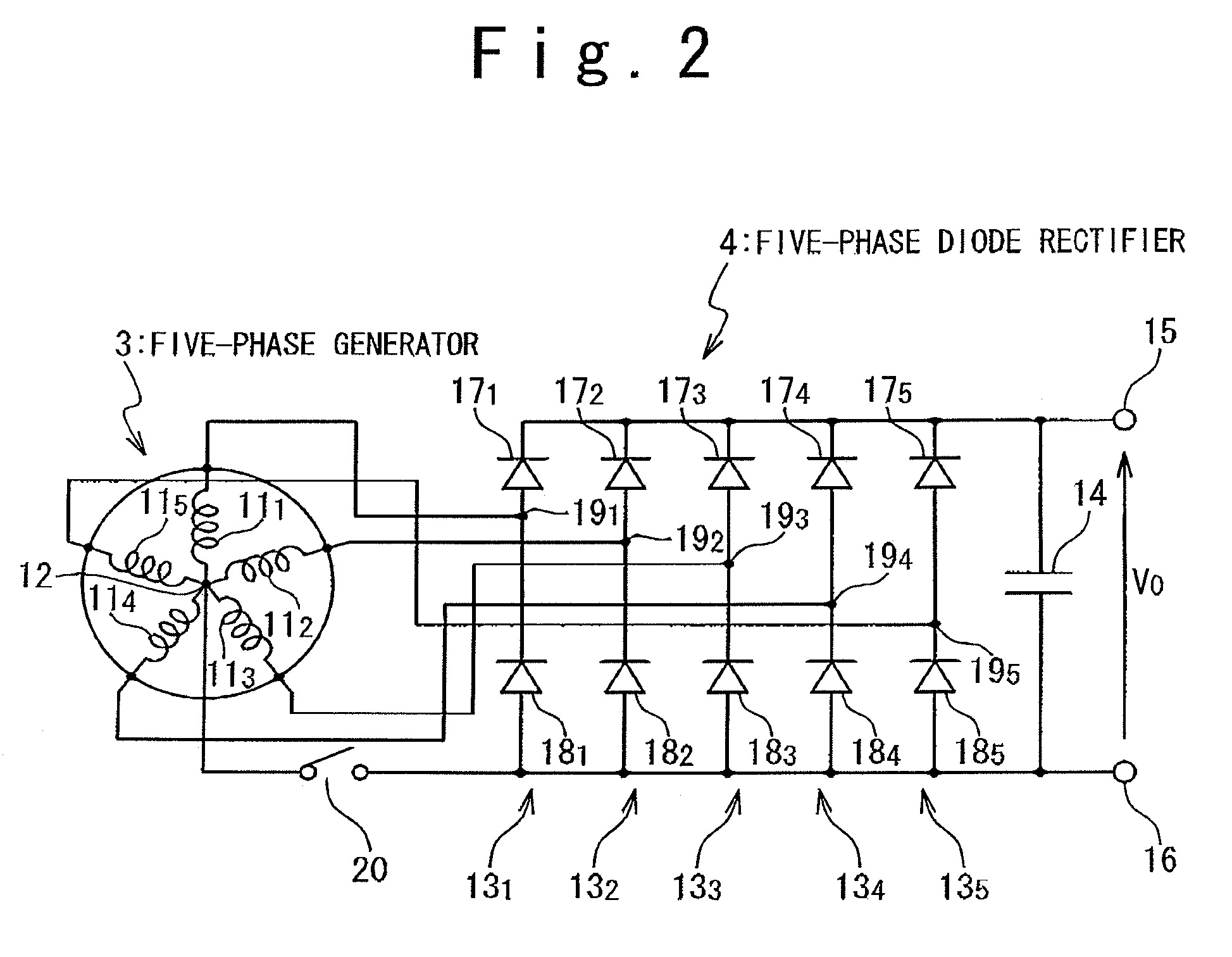
[0052]As mentioned above, the proper adjustment of the output voltage Vo outputted from the three-phase diode rectifier 4′ is important for protecting the battery 5. Similarly to the five-phase diode rectifier 4 of the first embodiment, a mechanism for adjusting the output voltage Vo is separately required, since the three-phase diode rectifier 4′ does not have the adjusting function for the output voltage Vo, by itself.

[0053]Prepared in this embodiment is a switching mechanism for switching the connections of the armature windings...


PUM


Abstract

There is provided a technique for improving the efficiency of a generation system of a series hybrid electric vehicle The series hybrid electric vehicle is composed of: an engine; an n-phase generator driven by the engine; a rectifier generating a DC voltage from an n-phase AC voltage received from the n-phase generator; a battery charged with the DC voltage generated; a motor driving drive wheels; an inverter driving the motor on the DC voltage received from the rectifier and / or a DC voltage supplied from the battery; and a switch. The n-phase generator has n armature windings each having one end connected to a common neutral point. The rectifier has a negative terminal, a positive terminal on which a higher potential is generated than on the negative terminal, and n rectifying arms. Each of the n rectifying arms includes; a first diode connected between an intermediated node connected to the other end of the corresponding armature windings and the negative terminal; and a second diode connected between the intermediate node and the positive terminal. The switch is connected between the neutral point and the negative terminal.

Description

RELATED APPLICATIONS[0001]The present application is a National Phase entry of International Application Number PCT / JP2005 / 000189, filed Jan. 11, 2005, which claims priority from, Japanese Application Number 2004-006047, filed Jan. 13, 2004, the disclosure of which is hereby incorporated by reference herein in its entirety.TECHNICAL FIELD[0002]The present invention is related to series hybrid electric vehicles, more particularly to a technique for improving energy efficiency of series hybrid electric vehicles.BACKGROUND ART[0003]The series hybrid electric vehicle designates an electric vehicle configured to drive an electric generator by an engine, to supply electric power from the electric generator to a motor, and to drive wheels by the motor, as disclosed in Japanese Laid Open Patent Application JP-A-Heisei, 4-322105, for example. In a series hybrid electric vehicle, the engine is dedicated to the electric generation, and the motive energy generated by the engine is not mechanica...

Claims


Application Information

Patent Timeline
Patent Type & Authority Patents(United States)
IPC IPC(8): B60K6/00B60K6/26B60K6/46B60K7/00B60K17/04B60L50/10B60L50/13B60L50/15B60W10/06B60W20/00F02D29/06F02D45/00H02K21/14H02P9/02
CPCB60K6/26B60K7/0007B60K17/043B60L11/123B60L15/2045H02K19/36H02P9/02H02P9/04H02P9/102H02P9/107H02P25/18H02P25/184B60K6/46Y02T10/7283B60K2007/0061B60L2210/30B60L2210/40B60L2220/46B60L2240/421B60L2240/423B60L2240/441F02D29/06H02K3/28Y02T10/6217Y02T10/7077Y02T10/7241Y02T10/645Y02T10/644Y02T10/641B60L2220/58B60L50/61Y02T10/62Y02T10/64Y02T10/70Y02T10/72Y02T10/7072
Inventor FUJIWARA, KENJIKOGURE, TAKATOSHIBABA, TUTOMU
Owner MITSUBISHI HEAVY IND LTD
Learn More