
In-line localized monitoring of catalyst activity in selective catalytic NOx reduction systems

a selective catalytic and catalyst technology, applied in the direction of material heat development, separation processes, instruments, etc., can solve the problems of reducing the efficiency of the catalyst, and increasing the cost of operation of the unit, so as to reduce or eliminate the deficiencies of the prior art method

Inactive Publication Date: 2009-12-22
FOSSIL ENERGY RES CORP
View PDF22 Cites 13 Cited by
  • Summary
  • Abstract
  • Description
  • Claims
  • Application Information

AI Technical Summary

Benefits of technology

Enables continuous, efficient monitoring of catalyst activity without shutdowns, providing precise data on degradation rates across different layers, reducing ammonia slip, and optimizing operational costs and compliance with emission regulations.

Problems solved by technology

This in turn results in greater amounts of unreacted ammonia leaving the unit (the “ammonia slip”) and therefore greater cost in operating the unit, a greater risk of pollution, and possible adverse impacts on downstream equipment.
Catalyst degradation is further complicated by the fact that in large catalytic reactors the catalyst is deployed in two or more distinct and separated layers, with different layers tending to degrade at different rates.
Monitoring methods that are in current use introduce inefficiencies of their own, however.
These methods will not differentiate between situations in which all catalyst layers are losing activity at approximately the same rate from those in which upstream layers are losing activity at a greater rate than those downstream.
A further difficulty is that increases in the ammonia slip or in the ammonia content of the fly ash may be the result of factors other than catalyst activity, such as an ammonia injection grid that is not properly adjusted or any other irregularity in the ammonia injection system.
Unless the unit is expressly shut down for the sampling, the time interval between sampling opportunities will be dictated by the outage schedule of the unit rather than concerns over the catalyst activity and can be very long.
A further problem with the withdrawal of catalyst samples is that the analyses of these samples provide no information regarding how any observed decrease in catalyst activity occurred, i.e., whether the decrease occurred slowly and gradually over time or by a step change resulting from a boiler upset, a fuel change, or some other occurrence not related to the SCR unit itself.

Method used


Image

  • In-line localized monitoring of catalyst activity in selective catalytic NOx reduction systems
  • In-line localized monitoring of catalyst activity in selective catalytic NOx reduction systems
  • In-line localized monitoring of catalyst activity in selective catalytic NOx reduction systems

Examples


example

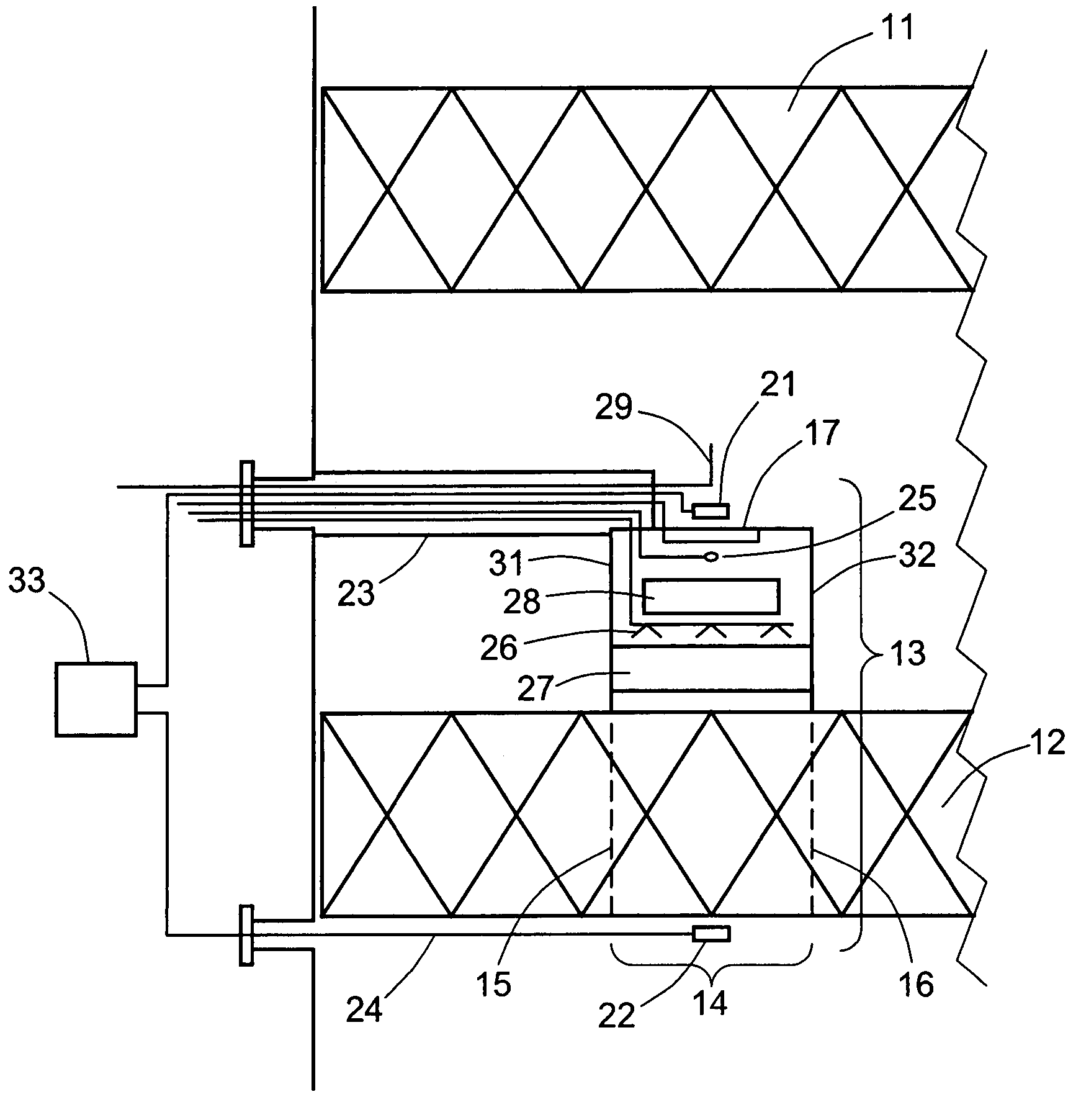
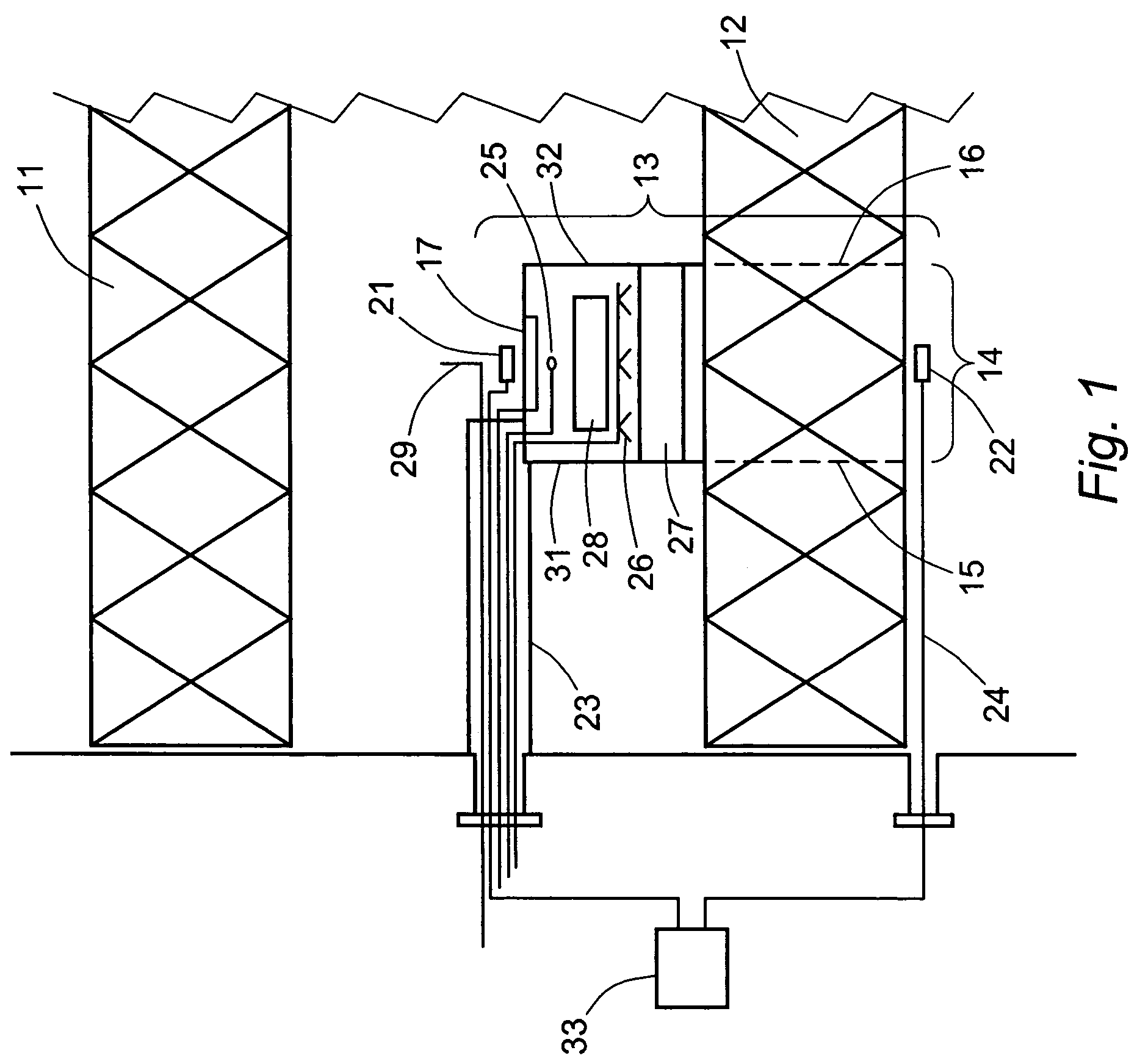
[0047]An example of a three-layer SCR unit is one that has flue gas flowing through the unit at a space velocity of 2,500 hour−1 (the volumetric flow rate of the gas at standard temperature and pressure divided by the catalyst volume) and a linear gas velocity of 15 ft / sec (4.6 m / sec), and whose inlet NOx level is 0.41 lb / 106 Btu (300 ppm at 3% O2), whose inlet NH3 / NOx mole ratio is 0.9, and whose temperature is 700° F. (370° C.). The gas flowing across the individual catalyst layers has the following composition parameters:

[0048]

Bed No.:123Inlet:mole ratio NH3 / NOx0.900.470.7ppm NOx3005732moles / min NOx0.00130.00020.0001Outlet:mole ratio NH3 / NOx0.470.07ppm NOx573230ppm NH3 slip26.632.280.00ΔNOx (%)81438

[0049]With modules on each of the three layers, each module being 2 feet square (0.4 square meter), the ammonia added to the module in each layer is as follows:


PUM

PropertyMeasurementUnit
lateral areaaaaaaaaaaa
heightaaaaaaaaaa

Abstract

Localized catalyst activity in an SCR unit for controlling emissions from a boiler, power plant, or any facility that generates NOx-containing flue gases is monitored by one or more modules that operate on-line without disrupting the normal operation of the facility. Each module is positioned over a designated lateral area of one of the catalyst beds in the SCR unit, and supplies ammonia, urea, or other suitable reductant to the catalyst in the designated area at a rate that produces an excess of the reductant over NOx on a molar basis through the designated area. Sampling probes upstream and downstream of the designated area draw samples of the gas stream for NOx analysis, and the catalyst activity is determined from the difference in NOx levels between the two probes.

Description

CROSS-REFERENCES TO RELATED APPLICATIONS[0001]This application is related to U.S. Provisional Patent Application No. 60 / 571,100, filed May 14, 2004, and claims all benefits legally capable of being offered by the provisional patent application. The entire contents of the provisional patent application are incorporated herein by reference.STATEMENT AS TO RIGHTS TO INVENTIONS MADE UNDER FEDERALLY SPONSORED RESEARCH OR DEVELOPMENT[0002]This invention was made with Government support under contract no. DE-FC26-05NT42298 awarded by the Department of Energy. The government has certain rights in this invention.BACKGROUND OF THE INVENTION[0003]1. Field of the Invention[0004]This invention resides in the field of NOx emissions from combustion facilities, and methods and plant equipment using selective catalytic reduction (SCR) for controlling and reducing the emissions.[0005]2. Description of the Prior Art[0006]A widely used process for the reduction of NOx emissions from coal-fired utility ...

Claims


Application Information

Patent Timeline
Patent Type & Authority Patents(United States)
IPC IPC(8): G01N31/10B01D53/30B01D53/56F01N3/10B01D53/86B01D53/90G01N1/22G01N33/00
CPCB01D53/8696B01D53/90G01N1/22Y10T436/207497Y10T436/177692Y10T436/175383Y10T436/179228Y10T436/20Y10T436/17Y10T436/178459
Inventor MUZIO, LAWRENCE J.SMITH, RANDALL A.
Owner FOSSIL ENERGY RES CORP
Learn More