Grave marker grid support system

a support system and grave marker technology, applied in the direction of traffic signals, road repairs, roads, etc., can solve the problems of constant maintenance, poor condition of some grave markers, and the possibility of tombstones falling and eventually sinking into the ground, so as to reduce the risk of damage, and be cost-effective

Inactive Publication Date: 2009-12-29
PLINTHS & CAISSONS
View PDF29 Cites 12 Cited by
  • Summary
  • Abstract
  • Description
  • Claims
  • Application Information

AI Technical Summary

Benefits of technology

[0004]The present invention discloses a method and system for maintaining the position of a grave marker in a cemetery. Previously, grave markers (headstones or tombstones) installed at a cemetery may shift over time. As the ground beneath the grave marker is subjected to erosion from frost, rain, snow, and wind, the grave marker may settle and eventually sink partially into the ground. Vandalism may also be a cause of the poor condition of some grave markers. In some cases the grave marker may become loose and fall, possibly getting damaged, causing constant maintenance. The present invention provides a subterranean bridge that the grave marker rests upon. In this way, the grave marker is supported by the bridge structure, and is less affected by soil conditions, and supported below frost levels. The bridge may be comprised of any suitable material that is strong enough to support the grave marker, and will not decompose when buried in the ground. In the currently preferred embodiment, concrete is used, as it has been shown to be a cost effective material to use to practice the present invention. Other materials, such as metal, fiberglass, or synthetic composites may also be used, provided they have the aforementioned strength and non-decomposition properties. Since, by definition, the grave markers are to be at the cemetery for an indefinite period of time, it is desirable to have a system to maintain the position of the grave marker for the long term. The bridge is comprised of two caissons and a plinth. The plinth is disposed in a horizontal orientation, straddling a caisson and a neighboring caisson, and the grave marker is supported by the plinth, which has drainage means to prevent standing water on the plinth, thereby reducing the risk of damage due to freeze-thaw cycles. The caissons are disposed in a vertical orientation at a predetermined distance from each other such that they may be assembled in a grid-like fashion that corresponds to the rows of grave markers in a cemetery layout. The grave marker is disposed within a socket on the plinth to further secure it, serving to make the grave marker more resistant to vandalism.

Problems solved by technology

As the ground beneath the grave marker is subjected to erosion from frost, rain, snow, and wind, the grave marker may settle and eventually sink partially into the ground.
Vandalism may also be a cause of the poor condition of some grave markers.
In some cases the grave marker may become loose and fall, possibly getting damaged, causing constant maintenance.

Method used


Image

  • Grave marker grid support system
  • Grave marker grid support system
  • Grave marker grid support system

Examples


embodiment 100

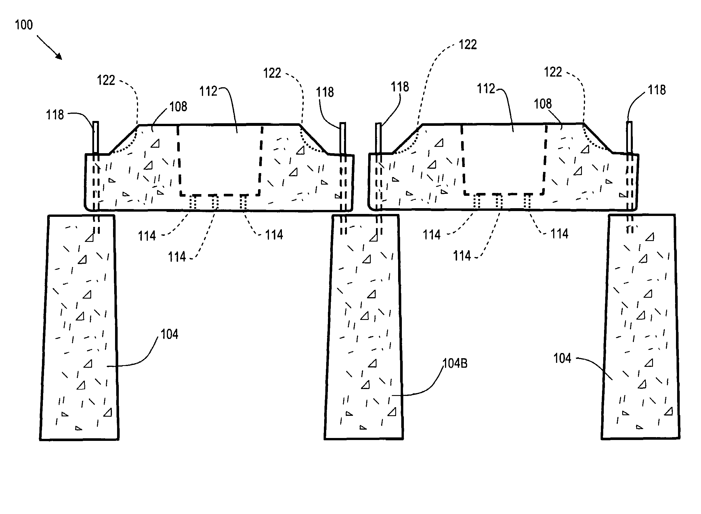
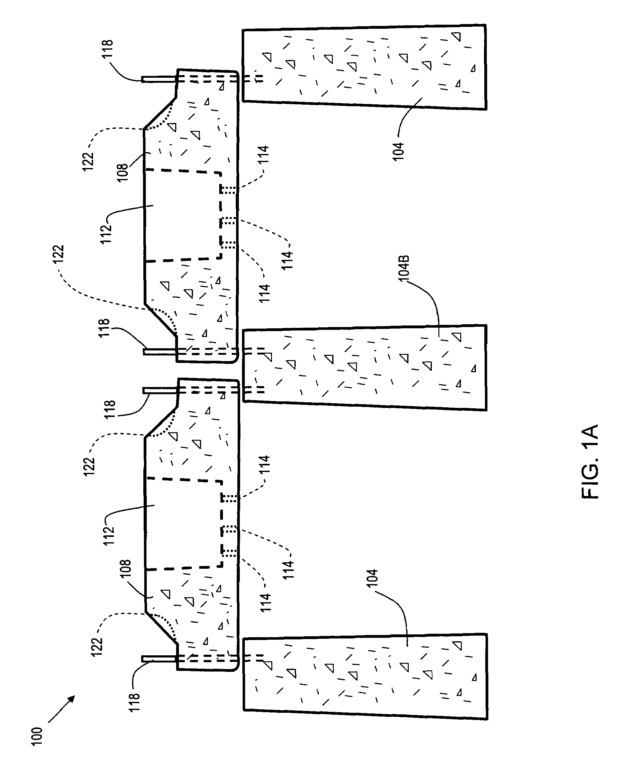
[0010]Referring now to FIG. 1A (side view) and FIG. 2 (top view), an embodiment 100 of a grave marker support system in accordance with the present invention is shown. Caissons (indicated generally as 104) serve as vertical support members. A plinth 108 is straddled across two caissons 104. The caissons 104 are sufficiently wide at the top thereof to provide support for two plinths, as is the case for caisson 104B. As stated previously, the caissons 104 and plinths 108 may be made of any suitable material with sufficient structural strength, and that will not decompose when buried. Concrete has been shown to be a cost effective building material that meets the aforementioned criteria for use in constructing the caissons 104 and plinths 108. In one embodiment, the caissons 104 are poured on site (at the grave site) into a forming structure (not shown), such as a “sonotube” manufactured by SONOCO PRODUCTS COMPANY of South Carolina, USA. Alternatively, the caissons 104 may be formed at...

embodiment 300

[0015]FIG. 3 shows a side view of an embodiment 300 of a grave marker support system in use with a grave marker 340 and casket 344. The base of socket (112 of FIG. 1) of plinth 108 is lined with a geotextile fabric material 332, such as one of the LINQ materials, manufactured by THRACE-LINQ INC, of Summerville S.C., USA. Geotextile fabric material 332 provides good drainage properties, allowing water to flow through it, yet keeps larger particulate matter from clogging drainage ports 114. Above geotextile fabric material 332 is a layer of small sized aggregate 336, such as a combination of one or more of cinder, crushed stone, quarry fines, stone dust, or small pebbles. Aggregate 336 provides a suitable means for fine adjustment of the position of grave marker 340.

[0016]In one embodiment, the type of quarry fines used is so-called “screenings.” Screenings are a uniformly sized, fine, sandy material with some silt particles. Screenings commonly range in particle size from about 3.2 m...

embodiment 400

[0019]FIG. 4 shows a side view of an additional embodiment 400 of a grave marker support system providing enhanced drainage capability. This embodiment is similar to the embodiment of FIG. 3, but having an additional aggregate layer 481 placed just below the plinth 108 to facilitate drainage. In one embodiment, the aggregate layer 481 is comprised of crushed stone, and has a depth that ranges from about 3 inches to about 5 inches.


PUM


Abstract

The present invention discloses a method and system for maintaining the position of headstones in a cemetery. Previously, headstones installed at a cemetery may shift over time. As the ground beneath the headstone is subjected to erosion from frost, rain, snow, and wind, the headstone may settle and eventually sink partially into the ground. In some cases the headstones may become loose and fall, possibly getting damaged. The present invention provides a subterranean bridge comprised of concrete that the headstone rests upon. In this way, the headstone is supported by the concrete bridge structure, and is less affected by soil conditions, ground water, and freeze-thaw cycles. Since, by definition, the headstones are to be at the cemetery for an indefinite period of time, it is desirable to have a system to maintain the position of the headstone for the long term. The bridge is comprised of two caissons and a plinth. The plinth straddles the caissons, and the headstone rests on the plinth, which has drainage means to prevent standing water on the plinth.

Description

FIELD OF THE INVENTION[0001]The present invention relates to a method and apparatus for supporting a tombstone.BACKGROUND[0002]In most instances when it is desired to support a marker above a filled excavation, a waiting period after the excavation has been filled is required before placing the marker. This waiting period is necessitated by the fact that after the excavation is filled, the fill dirt eventually settles changing the contour of the ground in the excavation area. Markers placed above the fill dirt before the settling period has terminated, sink and shift with the fill dirt.[0003]Another problem may be encountered in the case of a coffin placed directly in the ground without a burial vault. Coffins are generally made of wood, which eventually deteriorates in the ground causing the ground above the coffin to settle. This, as well as general soil erosion, can cause the grave marker to shift in position over time. Since, the grave marker (e.g. headstone, tombstone) is to re...

Claims


Application Information

Patent Timeline
Patent Type & Authority Patents(United States)
IPC IPC(8): E04H13/00
CPCE04H13/003
Inventor MURPHY, JOHNPOPLAR, JOSEPH
Owner PLINTHS & CAISSONS
Why Eureka
Try Eureka