Boot hanger mounting bracket

a technology for mounting brackets and boots, which is applied in the field of duct systems, register boots, and register boots, and can solve problems such as difficult storage, handling, and transportation without incurring damage of connections and fittings, and a risk of mounting or mounting a grille at an angle that is not secure enough to be used

Inactive Publication Date: 2010-01-12
APPLIED APPL INT LLC
View PDF54 Cites 23 Cited by
  • Summary
  • Abstract
  • Description
  • Claims
  • Application Information

AI Technical Summary

Benefits of technology

[0012]Advantages of the present invention include a simple versatile construction as well as facile rapid assembly. Another advantage of the present invention is that it may be stored and transported in a flattened state and can be adjusted on-site to provide an accurate fit between the boot register, grille and wall, floor, or ceiling opening, which reduces costs. Other features of the present invention are disclosed, or are apparent, in the section entitled “Mode(s) for Carrying-Out the Invention,” disclosed, infra.
is that it may be stored and transported in a flattened state and can be adjusted on-site to provide an accurate fit between the boot register, grille and wall, floor, or ceiling opening, which reduces costs. Other features of the present invention are disclosed, or are apparent, in the section entitled “Mode(s) for Carrying-Out the Invention,” disclosed, infra.

Problems solved by technology

Because the grilles generally must be mounted to the wall studs or ceiling joists, or to the ducts themselves, a risk exists that the grilles may be insecurely mounted or mounted at odd angles, particularly where the grilles are first attached and subsequently temporarily removed for wall painting or cleaning or other purposes.
First, the connections and fittings are difficult to store, handle, and transport without incurring damage.
In addition, due to their shape and design, they require a large quantity of space per unit to store and transport.
These problems cause the production of excessive scrap and increased inventory holding and transportation costs for the distributor and customers.
Additionally, the configuration of the ductwork and grilles poses a problem for unskilled construction workers and is extremely time consuming.
Because any measurements can introduce inaccuracies, the possibility that the components will not fit together or provide support for the grille register and boot in the wall or ceiling opening or create gaps between the edges of the opening and the grille register is a real concern.

Method used


Image

  • Boot hanger mounting bracket
  • Boot hanger mounting bracket
  • Boot hanger mounting bracket

Examples


example i

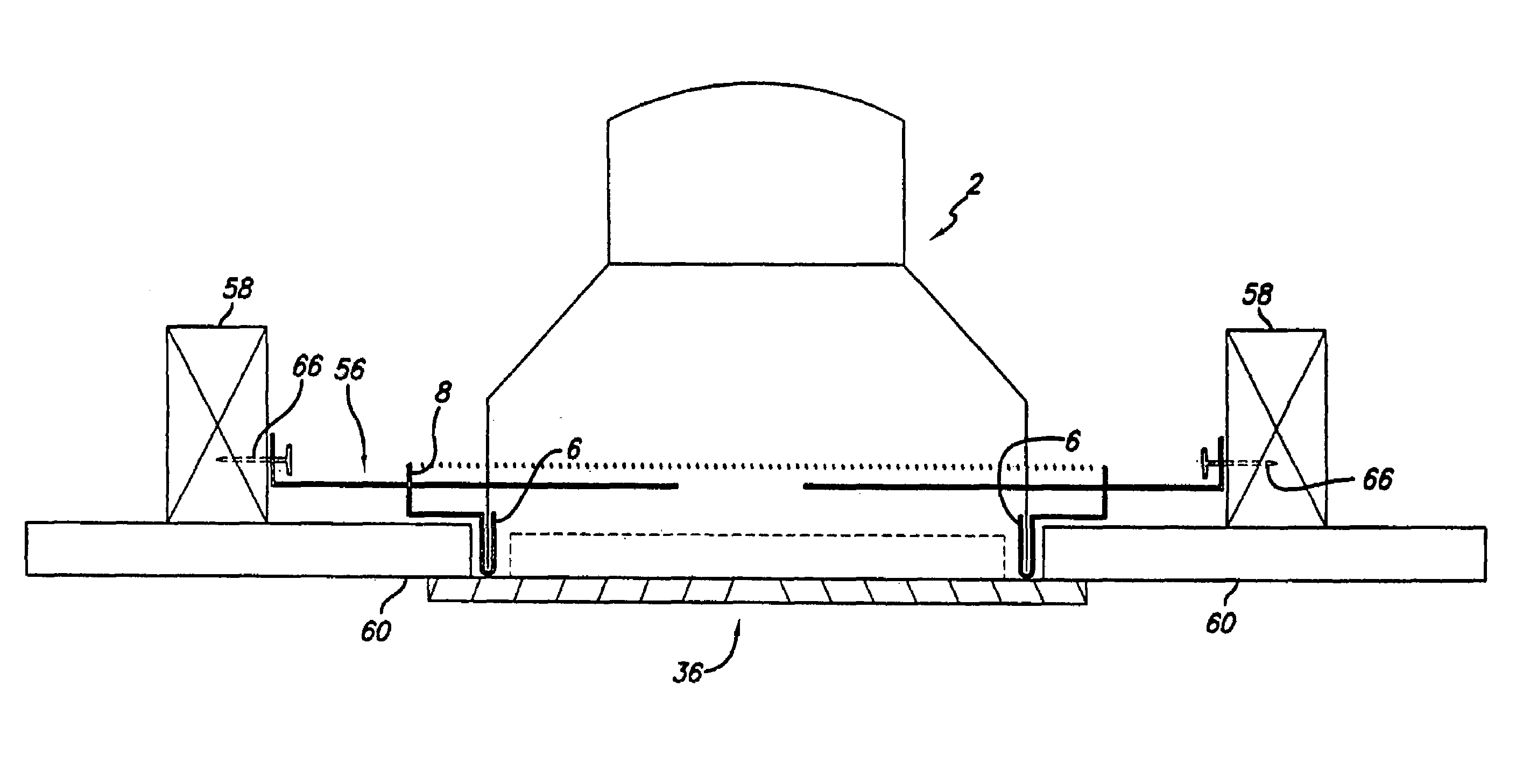
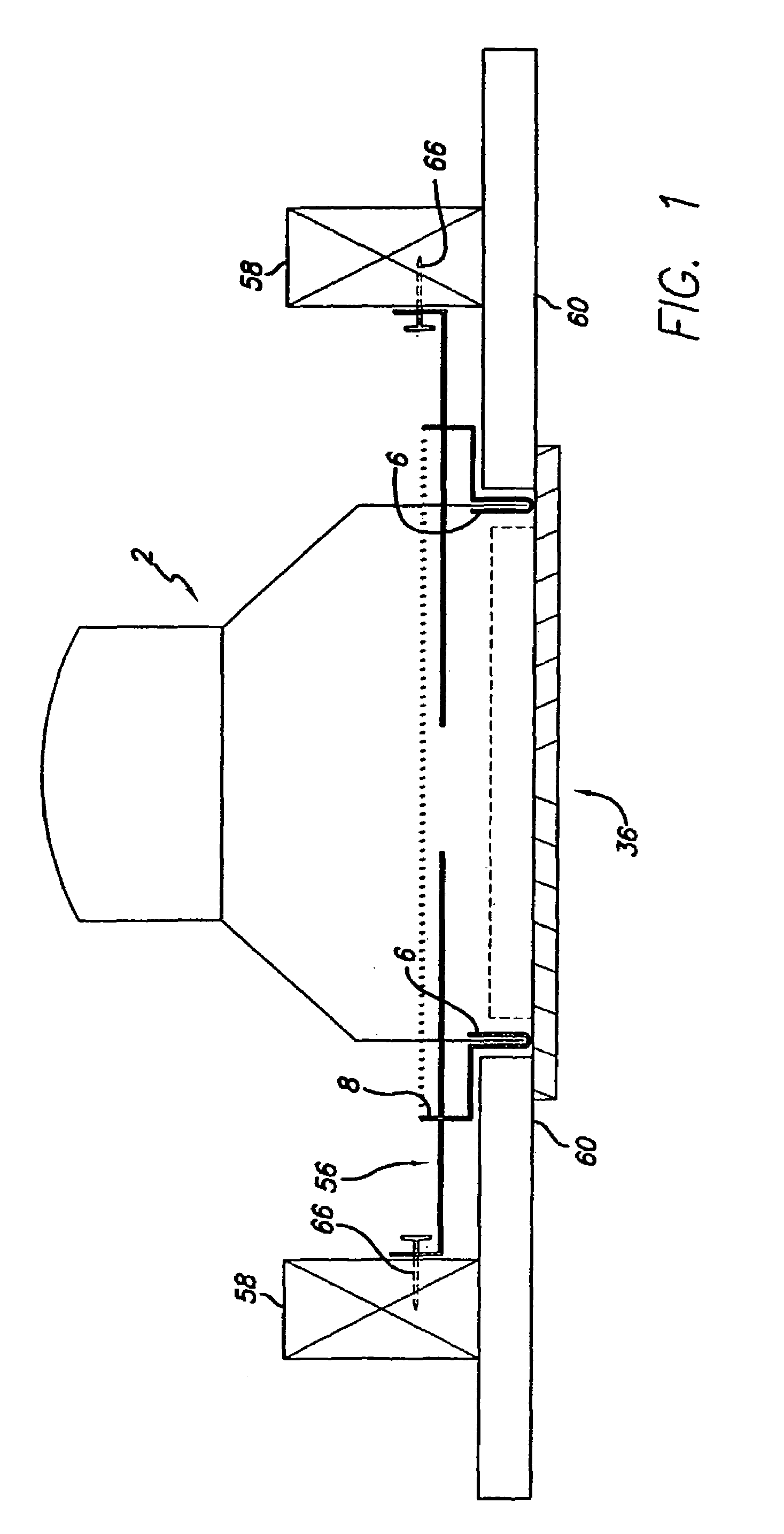
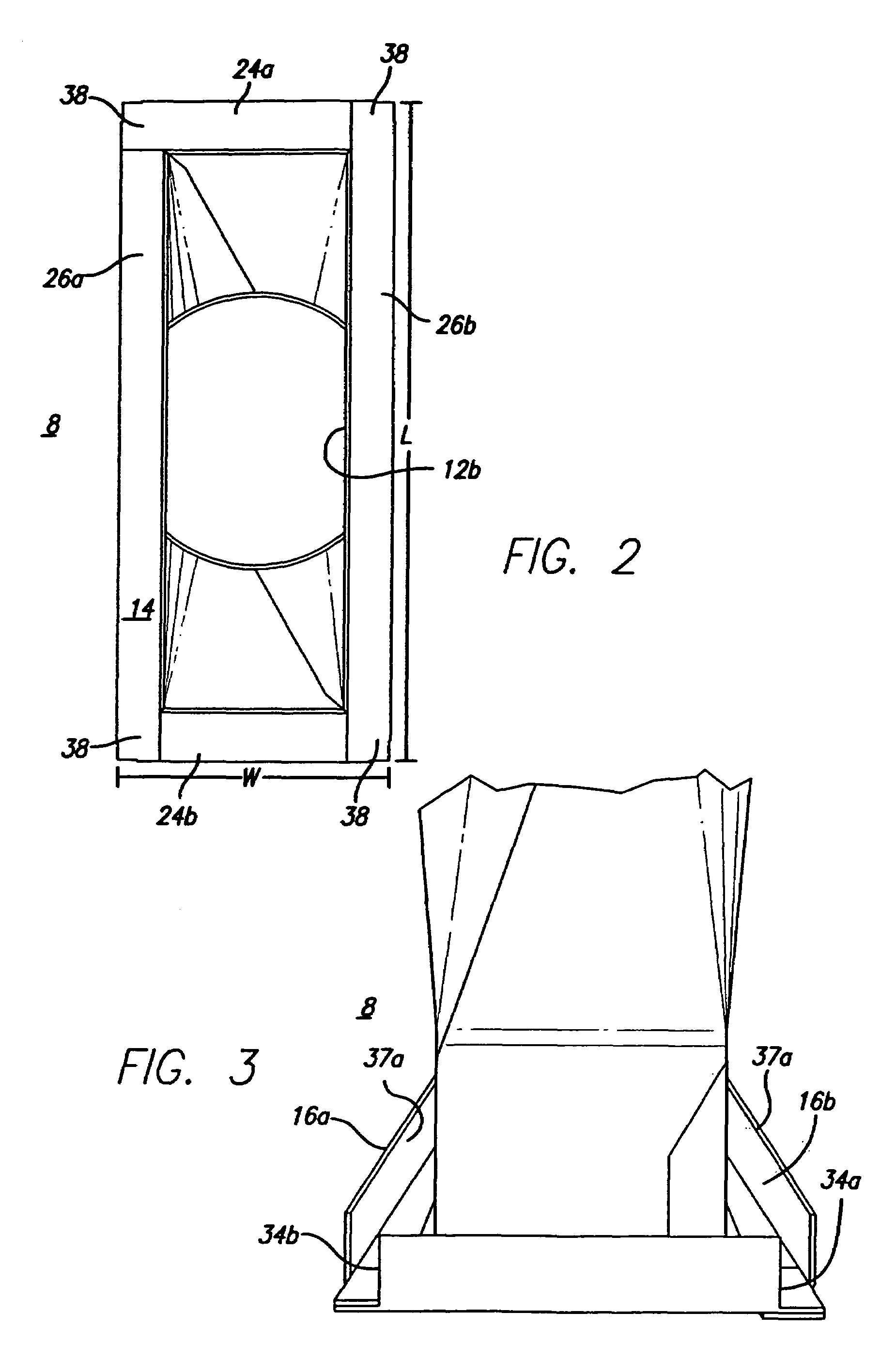
Dimensions of a First Version of Support Member and Boot Hanger Frame Portion for Boot Hanger Mounting Bracket Assembly

[0086]

DimensionApprox. Measurement in cmboot hanger frame portion width, w 20 cmrearward facing flange 16 along 20 cmwidth, w, of boot hanger frameportion (finished length)boot hanger frame portion length, l 36 cmrearward facing flange 18 along 36 cmlength, l, of boot hanger frameportion (finished length)Overlap portion 102 of lengthwiseApproximately 1 cm on each endflangesof flangeOpening 12b in finished boot hanger 30 cm (length) × 10 cm (width)mounting bracketSize of support member 6 along4.5 cm (width) × 29.5 cm (length)length, l, of boot hanger frameportion 8Size of support member 6 along4.5 cm (width) × 9.0 cm (length)width, w, of boot hanger frameportion 8Width of lip 502.5 cmTotal width of inner tab 42 and2.0 cmouter tab 48 of support member(s)Depth of pocket 46  1 cm

example ii

Dimensions of s Second Version of Support Member and Boot Hanger Frame Portion for Boot Hanger Mounting Bracket Assembly

[0087]

DimensionApprox. Measurement in cmboot hanger frame portion 8 width, w36 cmboot hanger frame portion 8 length, l36 cmOpening 12b in finished boot hanger30 cm (length) × 30 cm (width)mounting bracket 4

[0088]Information as herein shown and described in detail is fully capable of attaining the above-described object of the invention, the presently preferred embodiment of the invention, and is, thus, representative of the subject matter which is broadly contemplated by the present invention. The scope of the present invention fully encompasses other embodiments which may become obvious to those skilled in the art, and is to be limited, accordingly, by nothing other than the appended claims, wherein reference to an element in the singular is not intended to mean “one and only one” unless explicitly so stated, but rather “one or more.” All structural and functional...


PUM


Abstract

An adjustable boot hanger mounting bracket assembly comprising a boot hanger frame portion and a support member portion; the ductwork components, which may include a prefabricated can-boot / mud ring assembly; a pair of boot hanger arms; and a register grille. The boot hanger mounting bracket assembly is formed of a sturdy yet bendable material so that it can be configured and adjusted on-site. Once configured, the assembly is secured to the building structure by a securing a pair of boot hanger arms to the ceiling joists, wall studs, or other support structure. In this way, the boot hanger mounting bracket, through a direct attachment to the ceiling joist or wall stud, provides a positive inexpensive simple and error free way to mount the duct components.

Description

CROSS-REFERENCE TO RELATED APPLICATION(S)[0001]This document is a continuation-in-part application which is co-pending with, and claims priority from, U.S. patent application Ser. No. 10 / 828,077, also a continuation-in-part application entitled “Boot Hanger Mounting Bracket,” filed Apr. 19, 2004, now U.S. Pat. No. 7,140,960 which, in turn, claims priority from U.S. patent application Ser. No. 10 / 194,570, also entitled “Boot Hanger Mounting Bracket,” filed Jul. 11, 2002, both applications of which are incorporated herein by this reference thereto.TECHNICAL FIELD[0002]This invention technically relates to duct systems, registers and register boots, used as air ducts for warm air heating, ventilating, and / or air conditioning systems. More specifically, the present invention technically relates to improvements for mounting and installing the components of the duct system, including register boots, mud rings and air registers, in the walls, floors, or ceilings of buildings.BACKGROUND ART...

Claims


Application Information

Patent Timeline
Patent Type & Authority Patents(United States)
IPC IPC(8): F24F13/02F16L5/00F24F13/06
CPCF24F13/02F24F13/0254F24F13/06
Inventor PILGER, ALLAN
Owner APPLIED APPL INT LLC
Why Eureka
Try Eureka