
Method for calculating hydrogen temperature during vehicle fueling

a technology for gaseous hydrogen and vehicle fueling, which is applied in the direction of container filling under pressure, instrumentation, heat measurement, etc., can solve the problems of increasing temperature, increasing hydrogen consumption, and lack of hydrogen infrastructure to provide widespread generation, storage and distribution. , to achieve the effect of safe fueling experience and accurate and convenient calculation of the temperature of gaseous hydrogen

Inactive Publication Date: 2010-01-12
TEXACO INC
View PDF13 Cites 35 Cited by
  • Summary
  • Abstract
  • Description
  • Claims
  • Application Information

AI Technical Summary

Benefits of technology

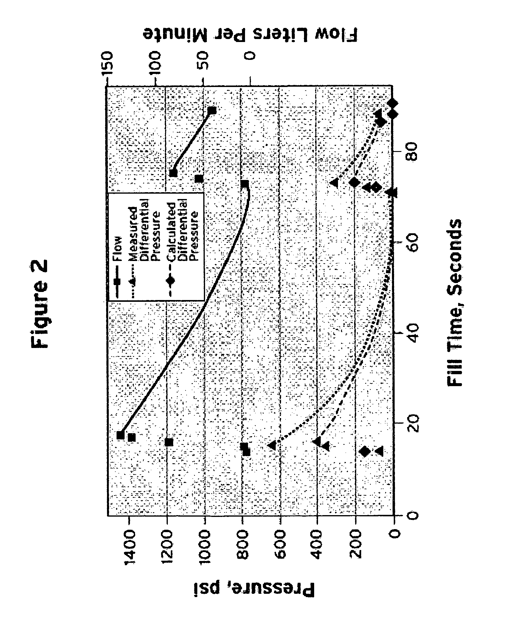
[0008]The metered amount of hydrogen added to the on-board storage tank, the ambient conditions, the pressure of the hydrogen at the dispenser, and a correlation to account for heat transfer are the inputs to the methods of the present invention. These inputs eliminate the need for obtaining temperature and pressure information from the vehicle. In addition, the use of the equation of the present invention does not require the fill rate to be limited and the corresponding fill time to be extended. Having an accurate calculation of the hydrogen temperature during vehicle fueling will provide a safe fueling experience.

Problems solved by technology

While there is wide-spread consumption of hydrogen and great potential for even more, a disadvantage which inhibits further increases in hydrogen consumption is the absence of a hydrogen infrastructure to provide widespread generation, storage and distribution.
This filling process causes an increase in pressure of the on-board storage tank of the vehicle and results in an increase in temperature due to the heat of compression of the hydrogen in the on-board storage tank.
However, the on-board storage tanks that are used, such as Type III tanks with an aluminum liner and a composite cover, are limited to 85° C.
First, limiting the fill rate results in long fill times. For example, the fill time can take up to twenty minutes.
Second, monitoring the temperature of the on-board storage tank requires the connection of a temperature sensor in the on-board storage tank to the dispenser.

Method used


Image

  • Method for calculating hydrogen temperature during vehicle fueling
  • Method for calculating hydrogen temperature during vehicle fueling
  • Method for calculating hydrogen temperature during vehicle fueling

Examples


Embodiment Construction

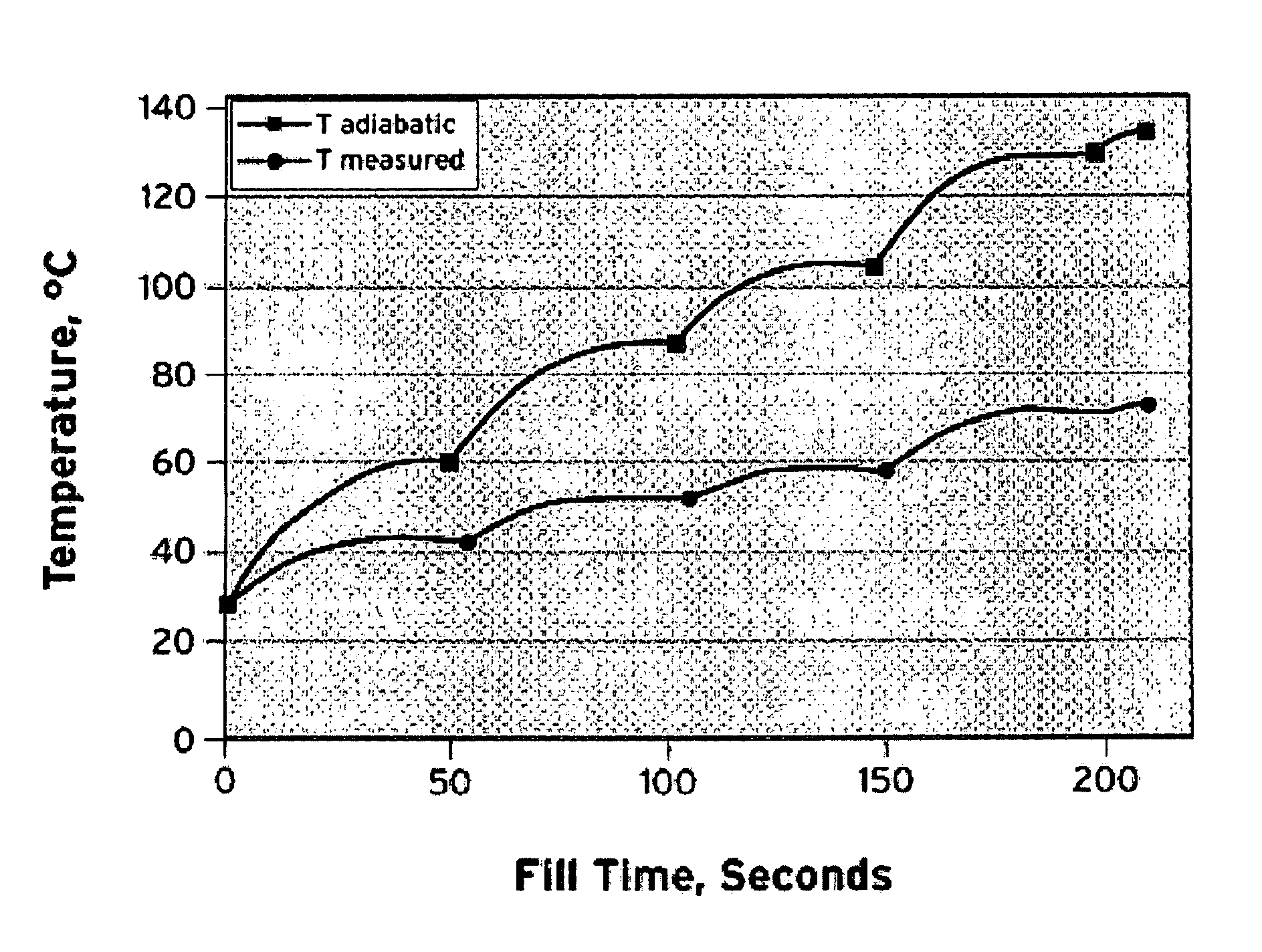
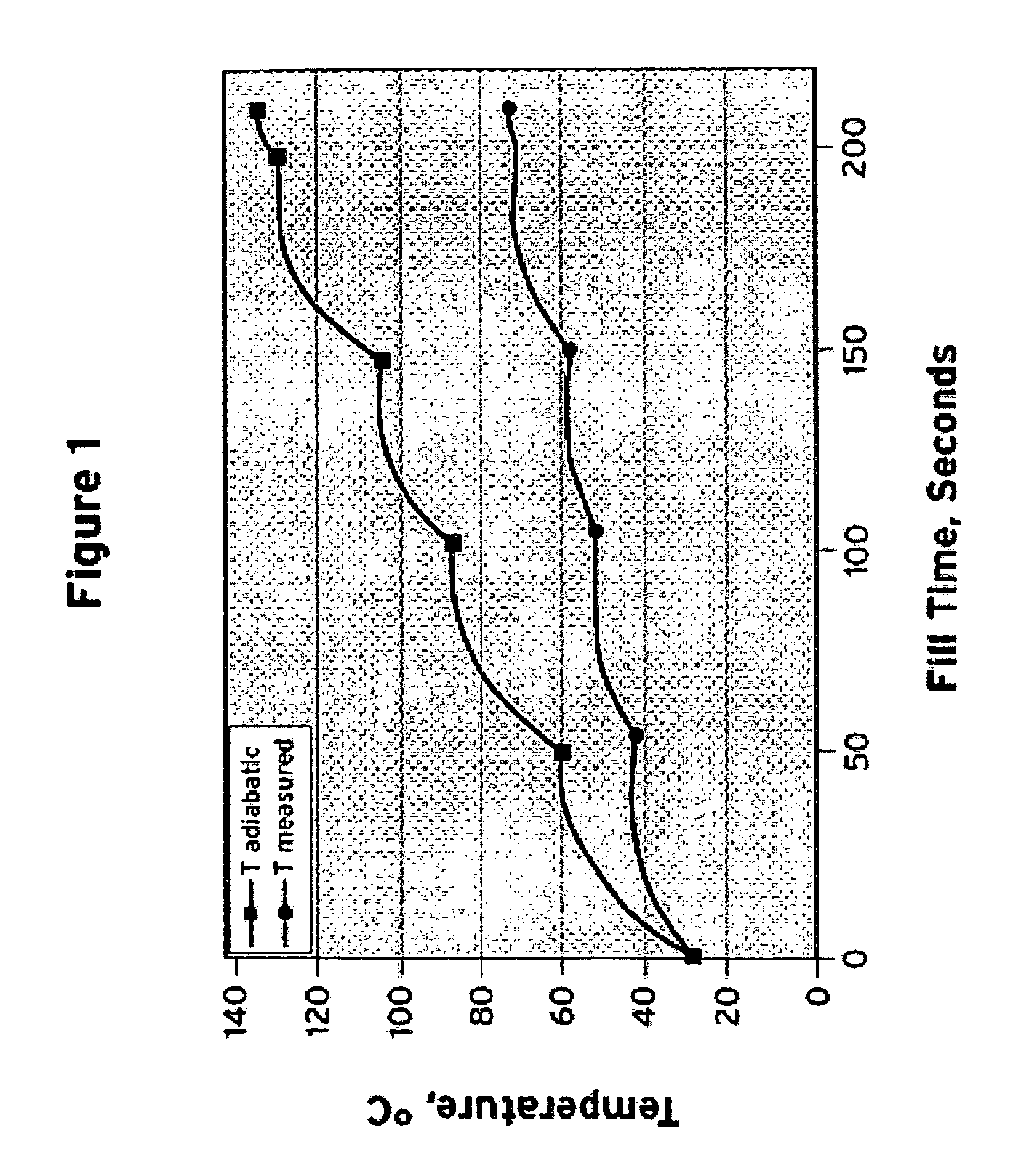
[0015]Gaseous hydrogen is transferred from a stationary storage vessel to a vehicle's on-board storage tank during vehicle fueling. The fill process must be controlled to prevent an over temperature of the on-board storage tank. In the present invention, methods for calculating the temperature of gaseous hydrogen during vehicle fueling are disclosed. The present invention discloses an equation that can be used to easily and accurately calculate the temperature of the on-board storage tank of the vehicle during vehicle fueling to allow for the safe fueling of the vehicle.

[0016]The present invention provides an accurate calculation of the heat balance of the filling process. This calculation takes into account the internal energy change of the vehicle on-board storage tank being fueled at the dispenser using pressure and temperature sensors located inside the dispenser. This calculation does not rely on pressure and temperature information provided by the vehicle. Using pressure and t...


PUM

PropertyMeasurementUnit
Temperatureaaaaaaaaaa
Volumeaaaaaaaaaa

Abstract

Methods for accurately and conveniently calculating the temperature of gaseous hydrogen during vehicle fueling are disclosed. The metered amount of hydrogen added to the on-board storage tank, the ambient conditions, The pressure measured at the dispenser, and a correlation to account for heat transfer are the inputs to the methods of the present invention. These inputs eliminate the need for obtaining temperature and pressure information from the vehicle which is out of the control of the dispenser and / or energy provider. In addition, the use of the equation of the present invention does not require the fill rate to be limited and the corresponding fill time to be extended.

Description

FIELD OF THE INVENTION[0001]The present invention relates to methods for calculating the temperature of gaseous hydrogen during vehicle fueling.BACKGROUND OF THE INVENTION[0002]Hydrogen is utilized in a wide variety of industries ranging from aerospace to food production to oil and gas production and refining. Hydrogen is used in these industries as a propellant, an atmosphere, a carrier gas, a diluents gas, a fuel component for combustion reactions, a fuel for fuel cells, as well as a reducing agent in numerous chemical reactions and processes. In addition, hydrogen is being considered as an alternative fuel for power generation because it is renewable, abundant, efficient, and unlike other alternatives, produces zero emissions. While there is wide-spread consumption of hydrogen and great potential for even more, a disadvantage which inhibits further increases in hydrogen consumption is the absence of a hydrogen infrastructure to provide widespread generation, storage and distribut...

Claims


Application Information

Patent Timeline
IPC IPC(8): G01K5/00
CPCF17C5/06G01K7/42F17C2201/054F17C2201/056F17C2203/0604F17C2203/0617F17C2203/0646F17C2203/0663F17C2221/012F17C2223/0123F17C2223/036F17C2225/0123F17C2225/036F17C2227/043F17C2250/0421F17C2250/043F17C2250/0439F17C2250/0631F17C2250/0694F17C2260/023F17C2260/026F17C2265/065F17C2270/0139F17C2270/0168Y02E60/321Y02E60/32
Inventor CASEY, DANIEL GLENNROVNER, JERRY MAXROBERTS, RANDY M.KRAUSE, CURTIS LEE
Owner TEXACO INC
Learn More