
Upgradeable, modular data center cooling apparatus

a data center and modular technology, applied in the field of computer data centers, can solve the problems and increasing the power density of the systems in the center, so as to achieve the effect of reducing the efficiency of air-cooling systems

Active Publication Date: 2010-01-19
HEWLETT-PACKARD ENTERPRISE DEV LP
View PDF7 Cites 43 Cited by
  • Summary
  • Abstract
  • Description
  • Claims
  • Application Information

AI Technical Summary

Problems solved by technology

Densification in data centers is becoming so extreme that the power density of the systems in the center is growing at a rate unmatched by technology developments in data center heating, ventilation, and air-conditioning (HVAC) designs.
Liquid-cooled computers could solve this heat transfer problem, however, there is reluctance by both end users and computer manufacturers to make the transition from air-cooled computers to liquid-cooled computers.
Also, there currently is no easy way to transition from an air-cooled data center to a liquid-cooled data center without a major overhaul of the data center and substantial down time to retrofit the data center.
However, these high heat capacity racks require extraordinary amounts of air to remove the heat dissipated by the racks, requiring expensive and large air handling equipment.
However, this type of system is limited in that it can only handle power of about 1600 to 2100 watts per square meter, significantly under the heat generated by many current electronic systems.
Also, use of the under floor plenum has difficulties in that airflow is often impeded by cabling and other obstructions residing in the plenum.
Further, perforated tiles limit airflow from the plenum into the data center to approximately 6 cubic meters per minute, well below the 60 cubic meters per minute required by some server racks.
Even the use of blowers to actively pull cold air from the plenum and direct it to the front of the rack is insufficient to cool many modern servers.
Balancing the airflow throughout the data center is difficult, and often requires a substantial amount of trial and error experimentation.
Finally, the airflow is somewhat inefficient in that there is a substantial amount of mixing of hot and cold air in the spaces above the servers and in the aisles, resulting in a loss of efficiency and capacity.
However this technique still has all of the inefficiencies of any raised floor plenum design and only increases the power handling capacity of the data center to about 3200 watts per square meter, still below the requirements of densely packed servers or telecommunication devices.
While this allows the use of large numbers of CRAC's without use of expensive data center floor space, it effectively acts as a large under floor plenum and is subject to the same inefficiencies and limitations of the under floor plenum design.
This results in less flexibility due to the presence of the liquid line and may require plumbing changes to the area where the rack is being moved to.
Also, this technique does not directly cool the heat generating integrated circuits, it is simply a heat exchanger which is not as efficient as direct liquid cooling of the integrated circuits.
However such overhead devices require a high ceiling that also must be strong enough to support the coolers.
Also, in such a design, there is no easy migration route from air-cooled to liquid-cooled servers, and some users are concerned about the possibility of leaks from the overhead coolers dripping onto, and possibly damaging, their servers.

Method used


Image

  • Upgradeable, modular data center cooling apparatus
  • Upgradeable, modular data center cooling apparatus
  • Upgradeable, modular data center cooling apparatus

Examples


Embodiment Construction

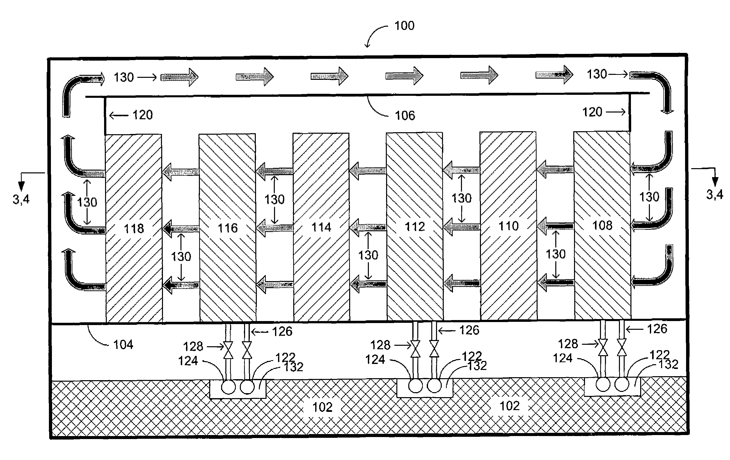
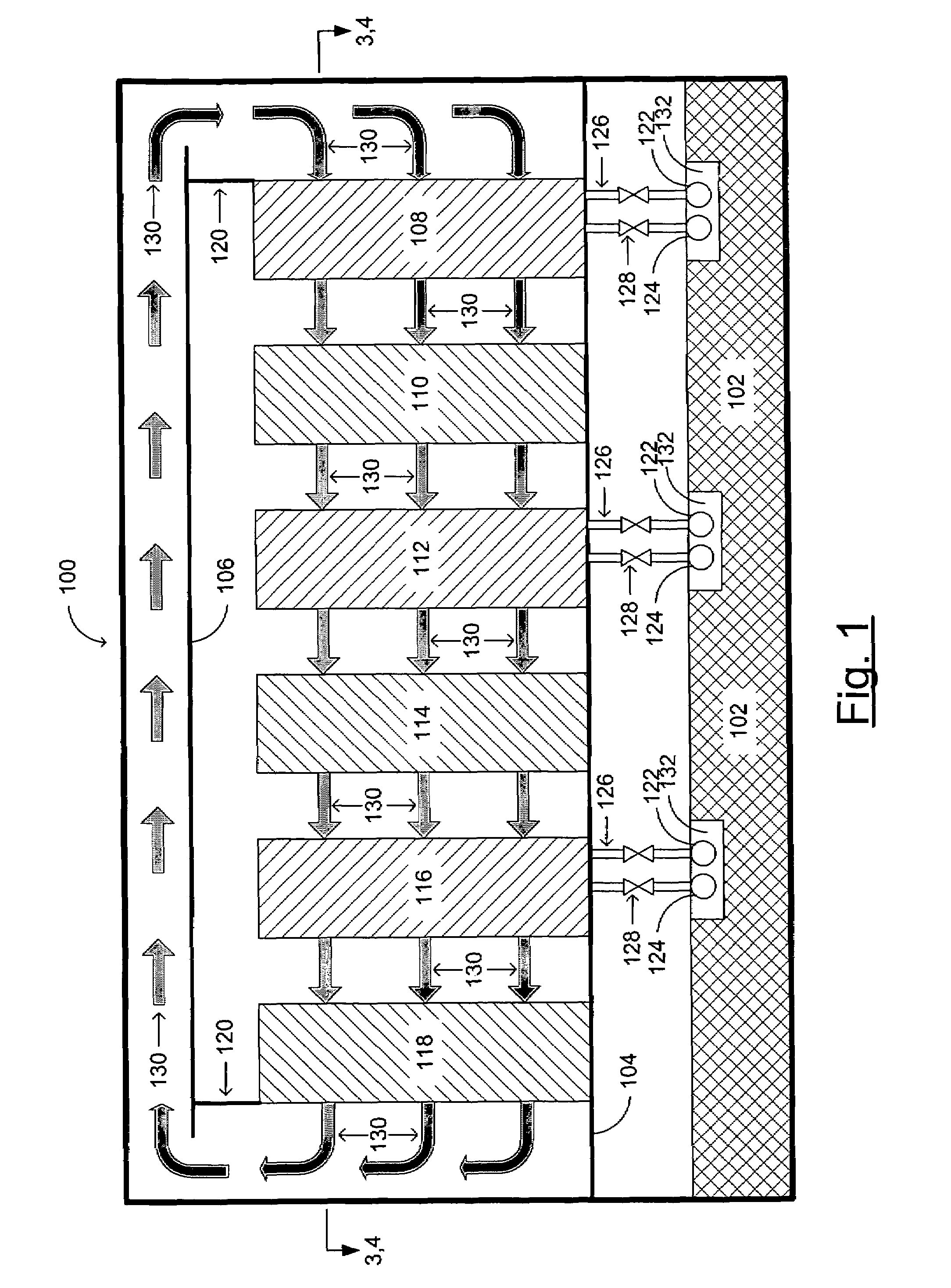
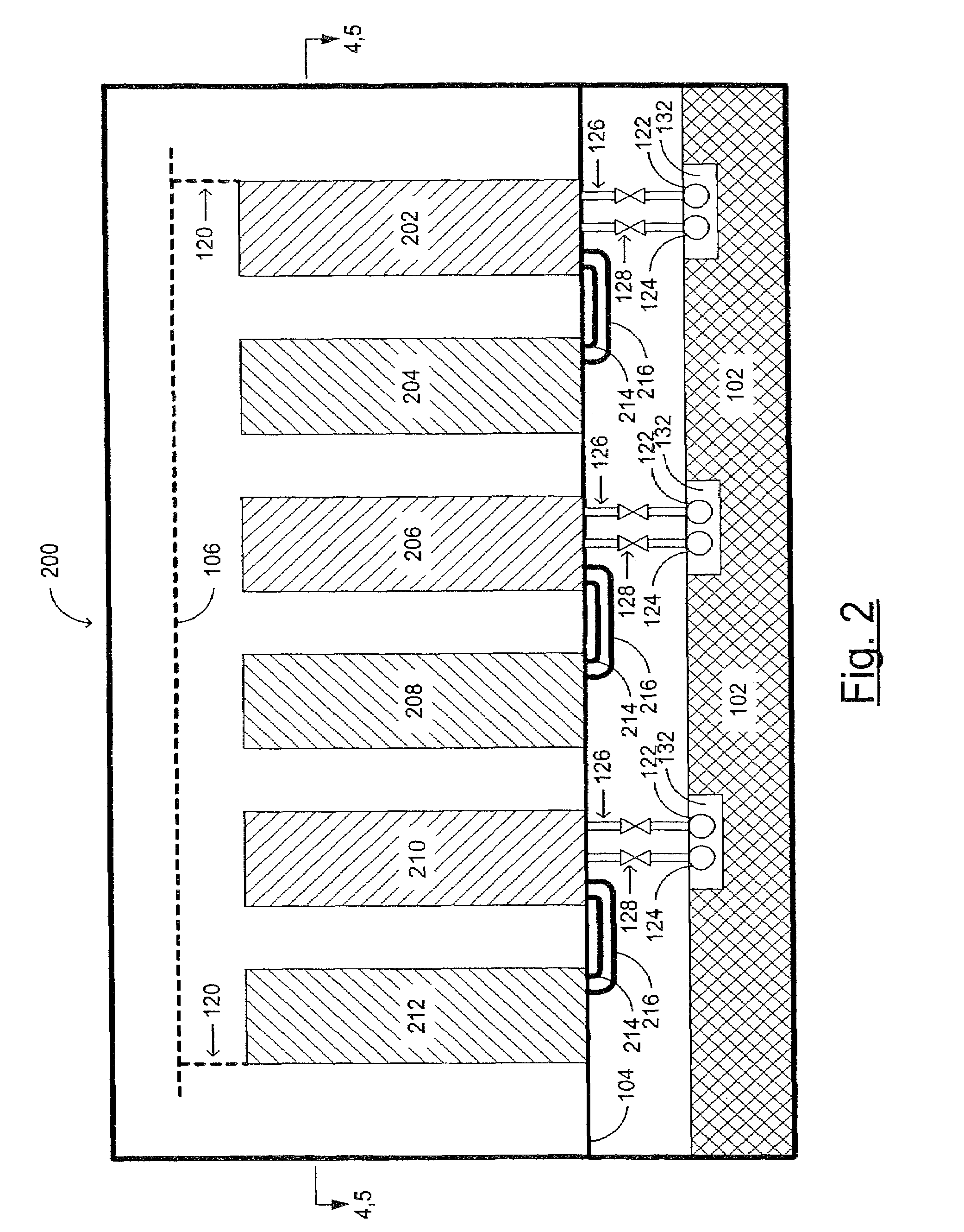
[0018]FIG. 1 is a side view of a data center including alternating air-cooled racks and 15 air conditioners according to the present invention. In this example embodiment of the present invention, a data center comprising a room 100 is built including a raised floor 104 and a foundation 102. Optionally, the room may include a false ceiling 106 for separation of the return airflow. Within the room 100 are a first air conditioning unit 108, a first rack 110, a second air conditioning unit 112, a second rack 114, a 20 third air conditioning unit 116, and a third rack 118. Note that in a typical data center each of these servers and air conditioning units are actually a single unit within a column of units. For example, the first rack 110 represented in this illustration may be a single server within a column of racks. See FIG. 3 for a top view of such a data center including three columns of racks and three columns of air conditioning units, one row of which is shown in FIG. 1. Airflow...


PUM


Abstract

A data center is configured using alternating rows of racks containing heat-generating electronic devices and air conditioners. Fluid, such as water or a refrigerant, for the air conditioners is supplied through pluming below a raised floor, such as those commonly found in current data centers. Attached to this plumbing are standard fluid couplings configured to couple to either air conditioners or liquid cooling units. These air conditioners and liquid cooling units use the same fluid so that they may share the plumbing. As data center migrates to liquid-cooled racks, a fraction of the air conditioners are replaced with liquid conditioning units in such a way that the data center contains both air-cooled and liquid-cooled racks without substantial reduction in efficiency of the air-cooling system. Since the air conditioners and liquid conditioning units use the same couplings and the same fluid, no infrastructure change is required.

Description

FIELD OF THE INVENTION[0001]The present invention relates generally to the field of computer data centers, and more particularly to the field of cooling computer data centers.BACKGROUND OF THE INVENTION[0002]Densification in data centers is becoming so extreme that the power density of the systems in the center is growing at a rate unmatched by technology developments in data center heating, ventilation, and air-conditioning (HVAC) designs. Current servers and disk storage systems generate 10,000 to 20,000 watts per square meter of footprint. Telecommunication equipment may generate two to three times the heat of the servers and disk storage systems. Liquid-cooled computers could solve this heat transfer problem, however, there is reluctance by both end users and computer manufacturers to make the transition from air-cooled computers to liquid-cooled computers. Also, there currently is no easy way to transition from an air-cooled data center to a liquid-cooled data center without a ...

Claims


Application Information

Patent Timeline
Patent Type & Authority Patents(United States)
IPC IPC(8): F25D23/12F24F3/06F25D3/02H05K7/20
CPCF24F3/06H05K7/20745H05K7/2079
Inventor BELADY, CHRISTIAN L.PETERSON, ERIC C.
Owner HEWLETT-PACKARD ENTERPRISE DEV LP
Learn More