Medical apparatus, use and methods

a technology of medical equipment and skeletal structure, applied in the field of medical equipment, can solve the problems of limited success of mechanical stimulus application by transducer methods of applying vertical compressive stress to the skeletal structure, inability to offer any variation of mono dimensional amplitude, and inability to achieve the effect of preventing secondary lymphoedema, facilitating the movement of interstitial fluid, and facilitating the patient's respons

Inactive Publication Date: 2010-01-19
MERLEX CORP PTY LTD
View PDF21 Cites 46 Cited by
  • Summary
  • Abstract
  • Description
  • Claims
  • Application Information

AI Technical Summary

Benefits of technology

[0018]In one preferred arrangement of either embodiment, the contact surface is toroidal, and encases the patient or part of the patient. Preferably in this form, the contact surface has an internal configuration adapted to closely conform with the anatomy of the patient, and so maximise the contact area with the patient.
[0047]According to yet another embodiment there is provided a method of preventing secondary lymphoedema including subjecting the patient to a complex pressure stimulus operating in multiple directions such that the epidermis, dermis and subcutaneous layers of the affected tissue are stimulated to the extent that there is a flexure in the tissue at a magnitude between about 0.5 mm and 3 mm, peak to peak, at a frequency of between about 1 and 50 Hz. Preferably, if the method were to be applied to a case of primary lymphoedema there would be a relatively rapid movement of interstitial fluid in the affected tissue into the lymphatic system.

Problems solved by technology

This form of vibration transducer can vary the frequency output but cannot offer any variation to the mono dimensional amplitude.
Another disadvantage of this form of vibration is that it can generate modal patterns which can make image interpretation difficult.
These prior art transducer methods of applying a vertical compressive stress to the skeletal structure have limited success in applying mechanical stimulus to the wider range of bones such as ribs and short plate like pelvic and hip bones to affect a change in bone rebuilding.

Method used


Image

  • Medical apparatus, use and methods
  • Medical apparatus, use and methods
  • Medical apparatus, use and methods

Examples


first embodiment

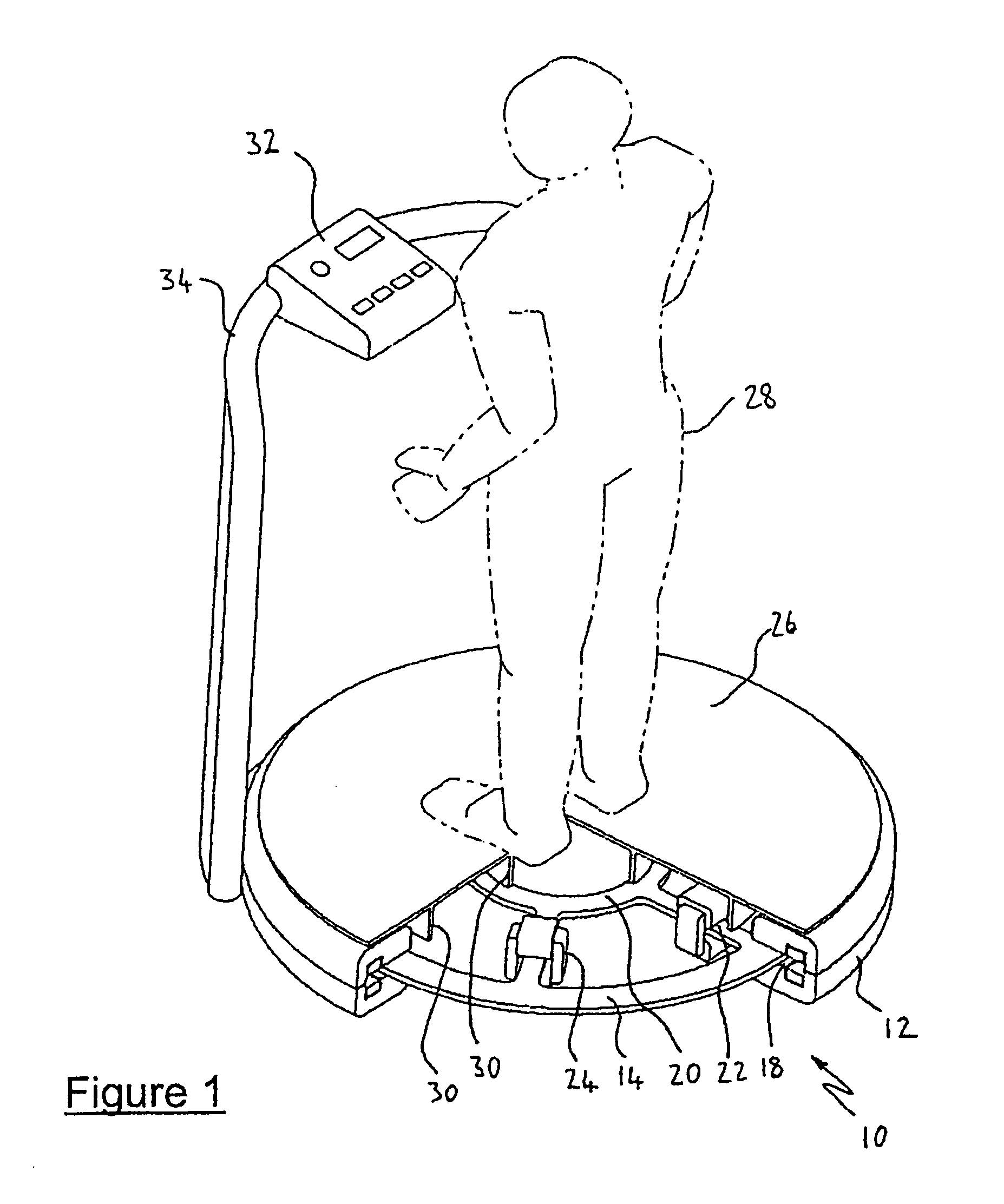
[0078]Referring to FIG. 1, the first embodiment shows apparatus used in a method of treating osteoporosis. The apparatus has a contact surface 26 on which a person 28 can stand. The contact surface is formed of a metal or non metal plate supported in insulating manner on circumferential rings 30 on the central hub 20 of the armature, and on the arms 22 adjacent the transformers 24, so that movement induced in the armature is transmitted to the contact surface 26. A microprocessor based controller 32 is mounted on a support frame 34, so that the movement of the armature can be programmed.

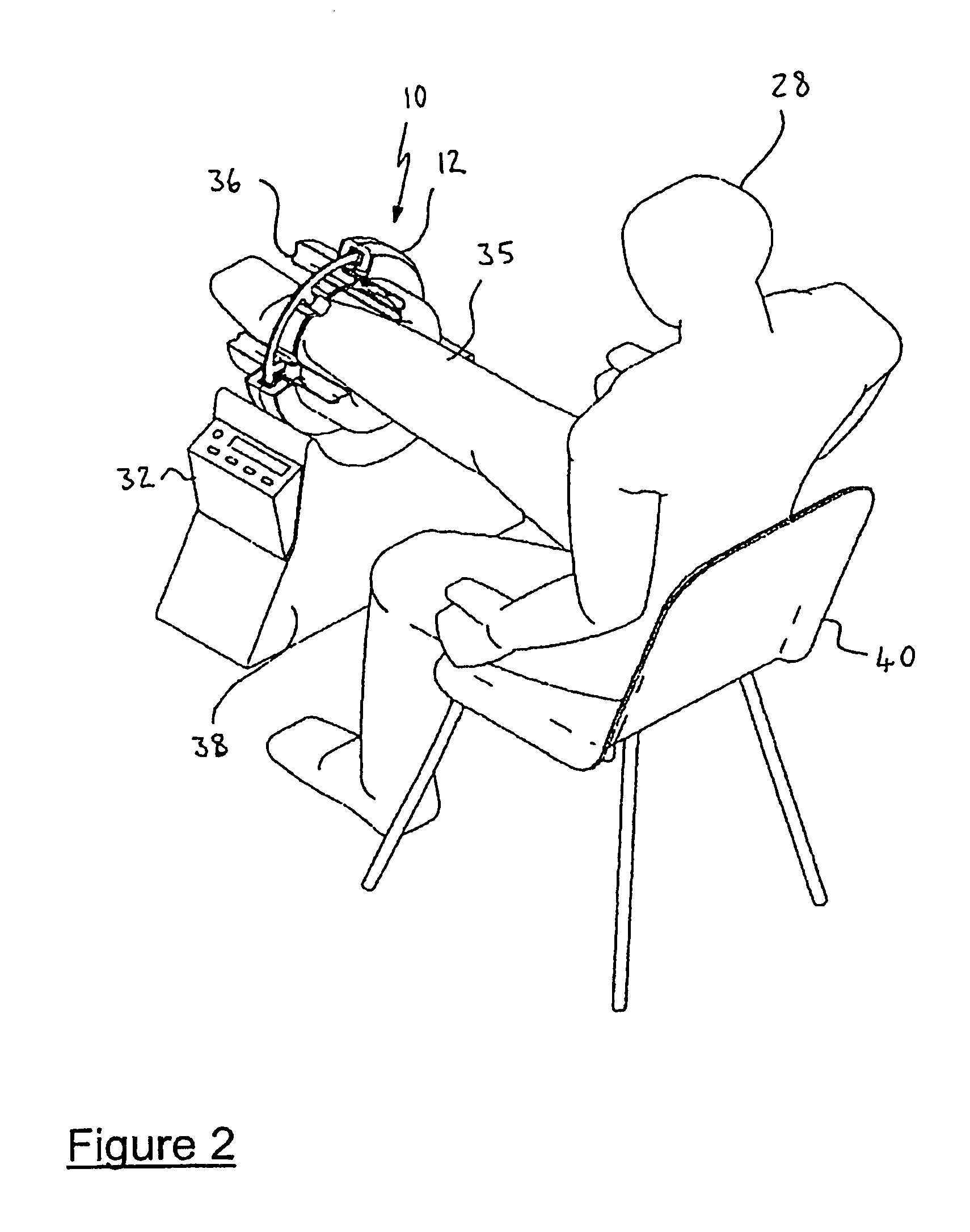
[0079]Referring to FIG. 2, the transducer 10 is mounted with its central axis disposed horizontally, so that a patient 28 can insert their leg 35, through the central hub 20. The apparatus shown in FIG. 2, which is intended to treat osteoporosis or lymphoedema includes the contact surface incorporated in bellows 36 formed of a composite foam rubber with inflatable cells, which is firmly fixed to the ...

fourth embodiment

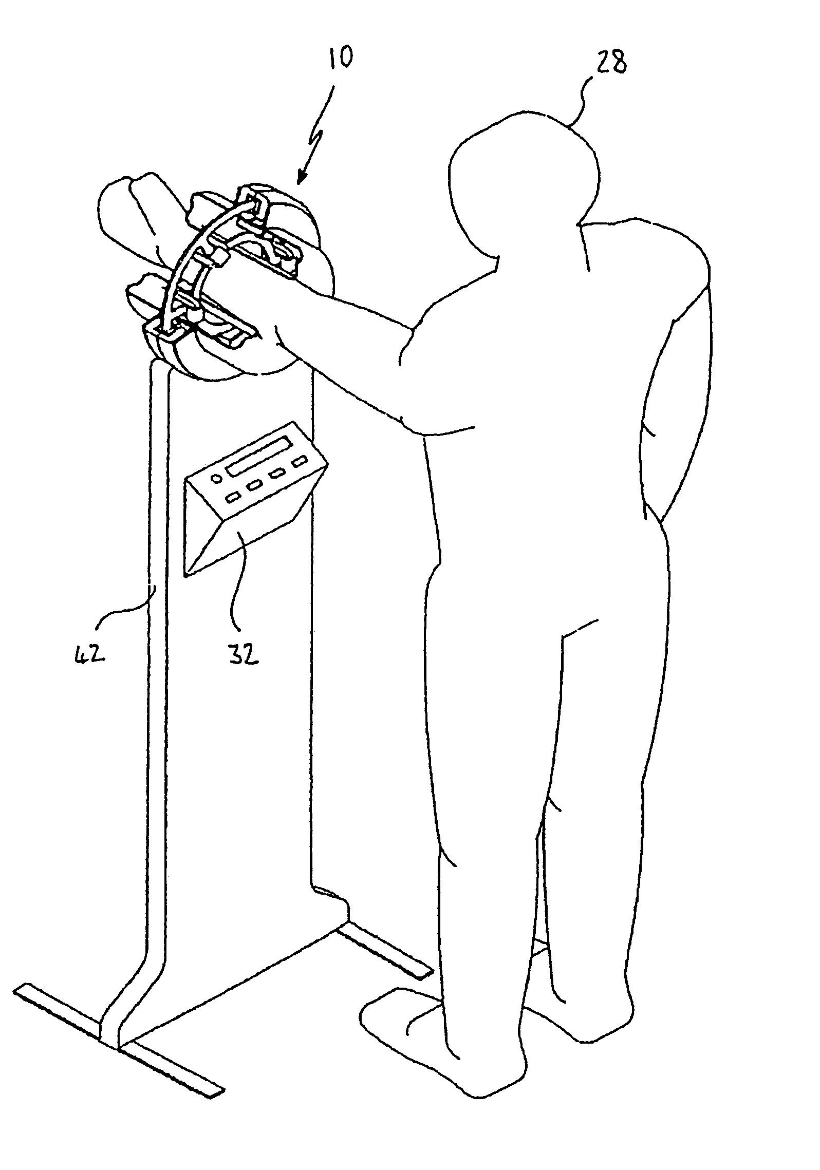
[0081]Referring now to FIG. 4, a fourth embodiment is shown for treatment of osteoporosis or lymphoedema, oedemas, muscle and tissue conditions and treatment of bone breakage and fractures and / or sonoelastography imaging. This embodiment differs in that it is mounted in a support frame which disposes a transducer 10 at a suitable height to receive the arm 44 of the patient 28, whilst standing.

fifth embodiment

[0082]Referring to FIGS. 5 and 6, the fifth embodiment is shown, which is shown being used in sonoelastography to induce vibration through the contact surface in the form of bellows 36, in a patient undergoing imaging by Doppler, ultrasound or magnetic resonance. In use, the patient lies through the bellows 36, resting on the bellows 36 with the region of their anatomy to undergo imaging, in close proximity to the bellows 36. This embodiment is also suitable for the treating of osteoporosis, muscle and tissue conditions or lymphoedema.

[0083]It should be noted that each of the embodiments has been shown cut away, so that internal details of the transducers can be seen. It will be understood that the transducer 10 is a circular device, the permanent magnet 12 being a full annulus, and the bellows completely surrounding the limb or body part to be imaged. The transducer can be constructed so as to be dividable, for transport. The embodiments shown in FIGS. 2 to 4 may be constructed so ...


PUM


Abstract

In accordance with one embodiment, a vibratory transducer has an armature suspended in a magnetic field. The armature has a plurality of electrical conductive paths to provide electrical current flow in said armature to react with said magnetic field and cause movement in the armature controlled by variation in the electrical current flow. A contact surface is secured to the armature, with a surface area for frictionally coupling to a corresponding surface area of a patient for example. Movement of the vibratory transducer induces movement in the patient, and the transducer can produce movement in the contact surface in at least two dimensions simultaneously. In one embodiment the contact surface is flat, while in alternative embodiments the contact surface is incorporated in a toroidal structure so as to surround part of the patient. Medical application can include treatment of bone fractures, oedema, and in elastography, amongst other applications.

Description

CROSS-REFERENCE TO RELATED APPLICATIONS[0001]The present application is a continuation of International Application No. PCT / AU2004 / 000680, filed May 21, 2004, which claims the benefit of Australian Application No. 2003902503, filed May 22, 2003.FIELD[0002]This invention relates to the field of medical apparatus, and particularly apparatus for imaging, and treatment. In particular this invention relates to use of a transducer for such imaging and treatment.[0003]This invention has particular application in imaging techniques such as sonoelastography, and treatment of conditions such as osteoporosis and oedemas such as lymphoedema.BACKGROUND ART[0004]Sonoelastography is an ultrasound imaging technique where low amplitude, and low frequency shear waves are propagated through organs and tissue while real time Doppler techniques are used to image the resulting vibration pattern. Hard lesions such as tumours in the presence of soft tissue, such in breast cancer, will have reduced vibratio...

Claims


Application Information

Patent Timeline
Patent Type & Authority Patents(United States)
IPC IPC(8): A61H1/00A61H19/00A61H7/00A61B8/08A61H23/02A61N2/04
CPCA61B5/0048A61B5/415A61B5/418A61B8/0825A61B8/0875A61B8/406A61B8/485A61B8/488A61H23/0218A61B5/4504A61B5/4519A61B5/0051
Inventor HOBSON, BARRY REGINALD
Owner MERLEX CORP PTY LTD
Why Eureka
Try Eureka