Multilayer filter

a filter and multi-layer technology, applied in the direction of overvoltage protection resistors, inductances, emergency protective arrangements for limiting excess voltage/current, etc., can solve the problems of varistor parts and inductor parts easily peeling off each other, affecting the material of inductor, etc., to achieve low dielectric constant, reduce peeling, and resistivity high

Active Publication Date: 2010-01-26
TDK CORPARATION
View PDF35 Cites 24 Cited by
  • Summary
  • Abstract
  • Description
  • Claims
  • Application Information

AI Technical Summary

Benefits of technology

[0012]In the multilayer filter according to the present invention, as described above, the elements of the varistor layer and inductor layer comprise the same material (ZnO) as a principal component. Therefore, even in the case where these are integrally sintered, the stress or the like based on the difference between volume change rates of the elements during sintering is less likely to occur between the two layers. As a result, the peeling is drastically reduced between the varistor part and the inductor part.
[0013]The material making the inductor layer, i.e., the material comprising ZnO as a principal component and substantially comprising neither Co nor Al, has characteristics of extremely high resistivity and low dielectric constant, when compared with a ZnO single body and the constituent material of the varistor layer (ZnO with additives of Pr or Bi, Co, and Al). Therefore, the inductor layer comprising the material comes to have excellent inductor characteristics.
[0014]More preferably, the multilayer filter of the present invention further comprises Li diffused from a surface to an interior. This makes the inductor part in the multilayer filter have much superior inductor characteristics. As a result, the multilayer filter becomes much superior in the characteristics to absorb noise and surge.

Problems solved by technology

In the foregoing conventional multilayer filter, however, the varistor part and the inductor part are different in materials making their elements, and thus levels of volume changes of them are largely different during the sintering.
Then this posed the problem that the varistor part and the inductor part were easy to peel off from each other.
However, the material making the element of the varistor part normally had a characteristic of extremely low resistance and was thus ill-suited for the material of the inductor.
For this reason, it was difficult to apply the multilayer filter of this type to high-frequency use.

Method used


Image

  • Multilayer filter
  • Multilayer filter
  • Multilayer filter

Examples


example 1

[0072](Fabrication of Multilayer Filter)

[0073]First, each of samples of the multilayer filter was produced according to the method described with FIG. 4 in the above embodiment. Specifically, the first step was to prepare the paste for formation of the varistor layers by adding Pr6O11, CoO, Cr2O3, CaCO3, SiO2, K2CO3, and Al2O3 into ZnO, and to prepare the paste for formation of the inductor layers by adding Pr6O11, Cr2O3, CaCO3, SiO2, and K2CO3 into ZnO.

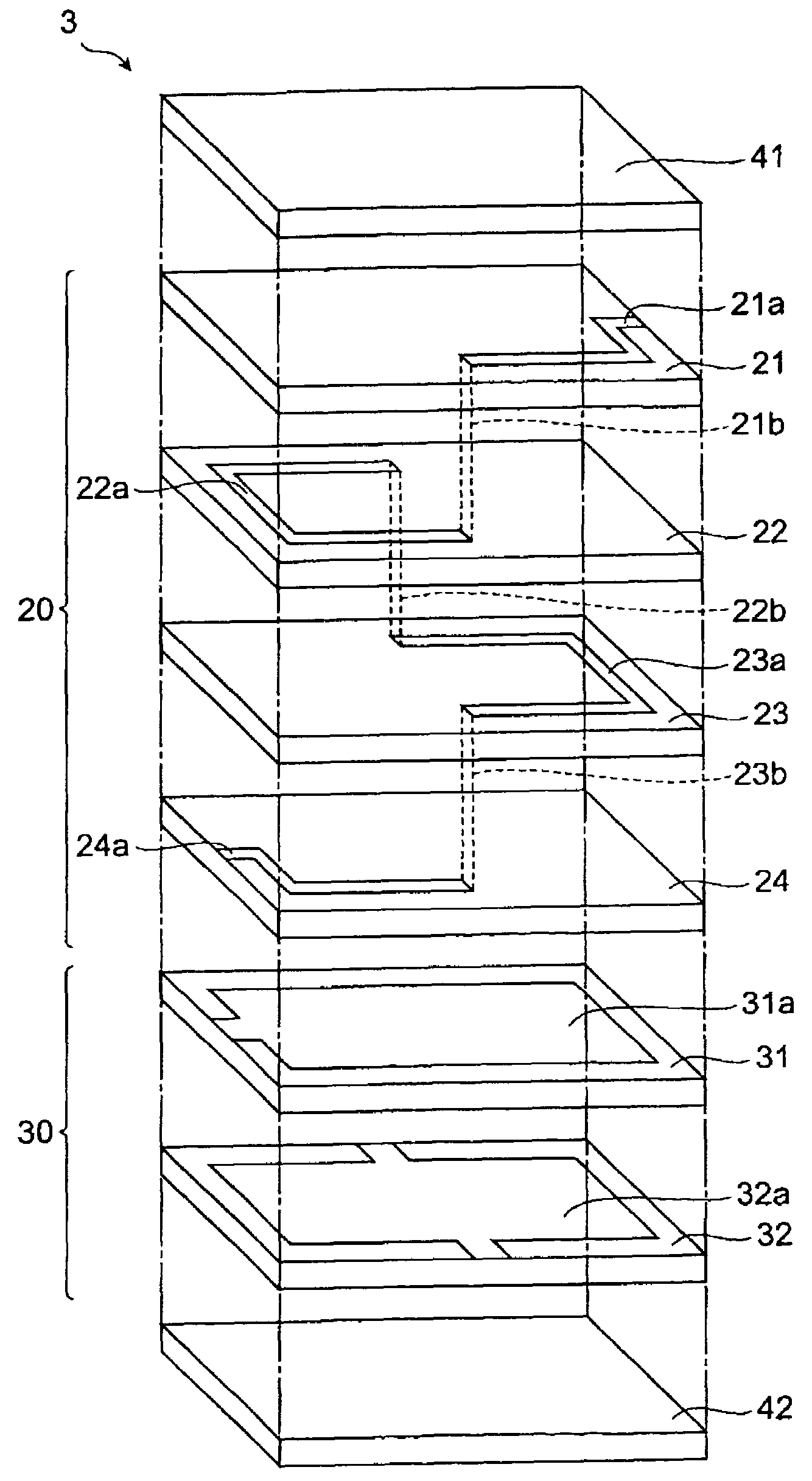
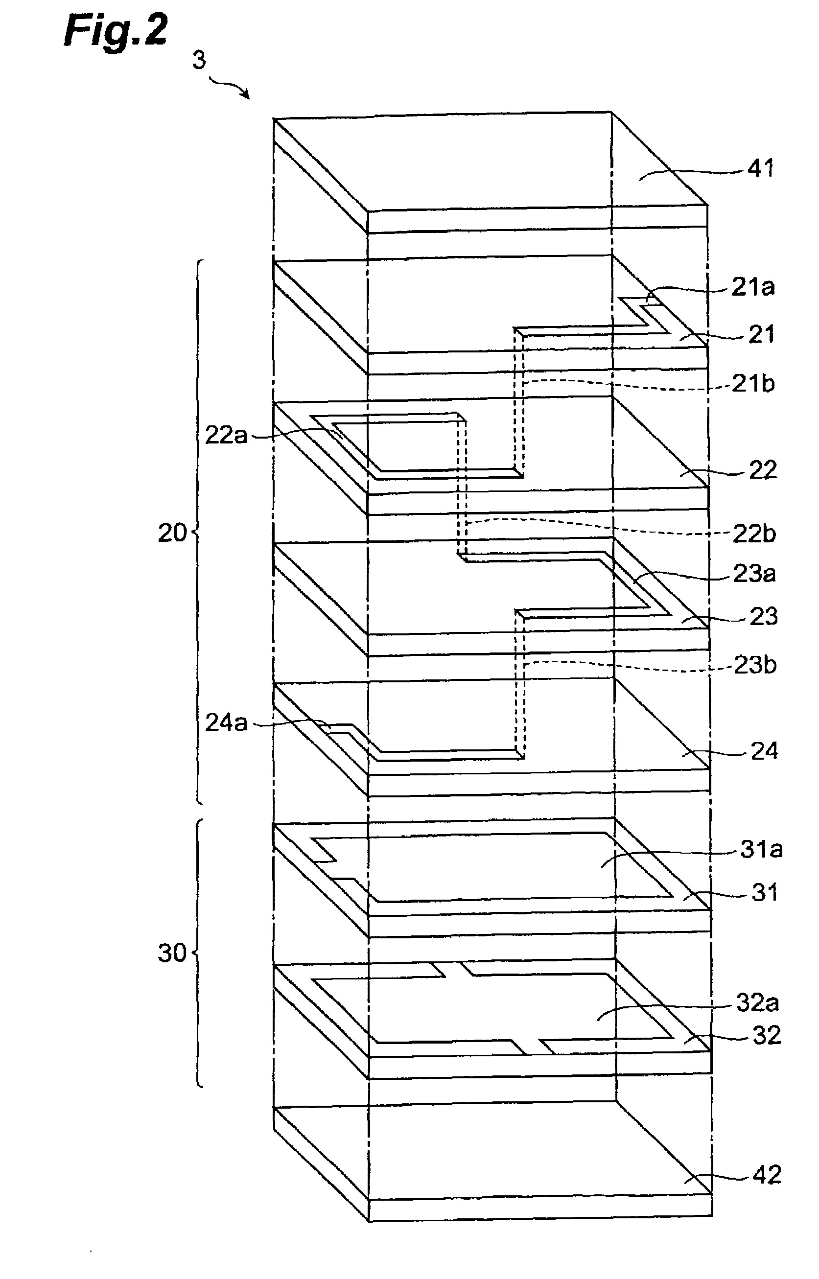
[0074]Subsequently, these pastes were used to produce the varistor sheets and inductor sheets. Together with these, green sheets for formation of the protecting layer containing only ZnO were produced. Thereafter, the conductive paste for formation of the internal electrodes (varistor part) or for formation of the conductor patterns (inductor part) was applied onto each sheet by screen printing so as to achieve the pattern as shown in FIG. 2. The paste for formation of the internal electrodes was one containing Pd as a principal comp...


PUM


Abstract

An object of the present invention is to provide a multilayer filter constructed so as to be less likely to suffer peeling between a varistor part and an inductor part. A multilayer filter 10 as a preferred embodiment has a structure in which a varistor part 20 and an inductor part are stacked. The varistor part 30 consists of a stack of varistor layers 31, 32 with internal electrodes 31a, 32a, and the varistor layers contain ZnO as a principal component, and contain at least one element selected from the group consisting of Pr and Bi, Co, and Al as additives. The inductor part 20 consists of a stack of inductor layers 21-24 with conductor patterns 21a-24a, and the inductor layers contain ZnO as a principal component and substantially contain neither Co nor Al.

Description

BACKGROUND OF THE INVENTION[0001]1. Field of the Invention[0002]The present invention relates to a multilayer filter and, more particularly, to a multilayer filter consisting of a stack of a varistor part and an inductor part.[0003]2. Related Background Art[0004]In recent years, electronic devices have been and are being developed toward higher frequencies of transmitted signals for fast operation, toward lower voltages for power saving, and so on. Under such circumstances, the technology of removing noise, surge, etc. is becoming more and more important for the electronic devices, in terms of securing excellent reliability. Then a multilayer filter consisting of a stack of a varistor part and an inductor part is drawing attention as an element capable of removing both noise and surge by a single chip.[0005]One of the known multilayer filters of this type is a composite function element obtained by joining a ceramic porcelain and a magnetic material porcelain and integrally sinterin...

Claims


Application Information

Patent Timeline
Patent Type & Authority Patents(United States)
IPC IPC(8): H01C7/00
CPCH01C7/1006H01C7/18H01C13/02H03H7/09H03H7/1708H03H7/1758H01F27/40H03H2001/0085H01F2017/0026H01C7/10H01L27/02H01F17/00
Inventor MORIAI, KATSUNARIMATSUOKA, DAISATO, TAKAHIRO
Owner TDK CORPARATION
Why Eureka
Try Eureka