Supercharge Your Innovation With Domain-Expert AI Agents!

Bidirectional optical fiber link systems component couplers

a technology of bidirectional optical fiber and component coupler, which is applied in the direction of optics, optical light guides, instruments, etc., can solve the problems of fiber breakage, reduced service life of optical fiber, and limited range of optical fibers located on the edge of printed circuit board based systems

Active Publication Date: 2010-02-02
VIXAR
View PDF7 Cites 51 Cited by
  • Summary
  • Abstract
  • Description
  • Claims
  • Application Information

AI Technical Summary

Benefits of technology

The present invention is a device that connects an optical fiber to a signaling device. It uses an optical element to send and receive signals between the fiber and the device. This optical element prevents signals from interfering with the device. The device is housed in a molded part that aligns with the fiber. The technical effect of this invention is to create a reliable and efficient connection between an optical fiber and a signaling device.

Problems solved by technology

The most difficult requirements to be met in implementing the link system shown in FIG. 1 come from the need to couple light from optical emitter 2 into optical fiber 4, and to direct the light emerging from that fiber onto photodetector 5.
For example, transceivers located on the edge of a printed circuit board based system are often limited by the amount of space available for connections thereto at the edge of the board.
Alternatively, for longer distance connections, the cost of the optical fiber used becomes substantial.
These issues can include fiber breaks, excessive fiber bends, and dirty or damaged fiber connectors.
However, the “wiring closets”, or spaces where network equipment is located, are often cramped and stuffed to capacity with such equipment which could be alleviated to an extent by the use of bidirectional transmissions on individual optical fibers to thereby reduce the number of them used and the associated connectors and the like.
The increasing density of components and their interconnections occurring in more recently provided ones of such wiring cabinets raises the costs of any troubleshooting undertaken with respect thereto.
Gaining access to the various points of a link in a military aircraft, for instance, can be very difficult.
These lasers provide a combination of good performance at a reasonable cost for these shorter distance links, but typically do not provide sufficient performance for long distance telecommunication fiber optic links due to the mismatch between the laser emission wavelength and the optical fiber best transmission wavelengths (850 nm versus the desired 1310 nm or 1550 nm) and the wider laser emission spectral width as compared to the fiber transmission spectral widths at these wavelengths.
For instance, reflected light from the fiber directed back into the aperture of the optical emitter can cause noise in that optical emitter thus degrading the information carrying capacity of the link.
Housings or packages are available for components used in coupling to optical fibers in bidirectional fiber optic links, including those that incorporate OTDR capability into a fiber optic transceiver, but they tend to be expensive, bulky and designed for use with EELs.
However, use of a VCSEL both as a laser and as a photodetector requires some (often unacceptable) compromises to be made in the device structure resulting in either an inferior laser, an inferior photodetector, or both.

Method used


Image

  • Bidirectional optical fiber link systems component couplers
  • Bidirectional optical fiber link systems component couplers
  • Bidirectional optical fiber link systems component couplers

Examples


Embodiment Construction

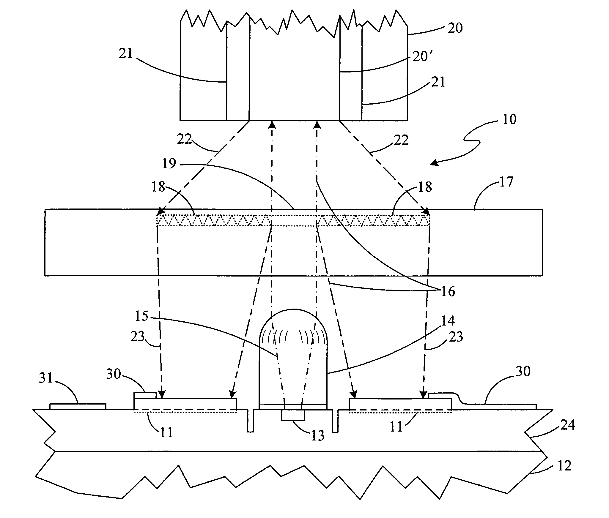
[0045]An embodiment of the present invention as a combined laser and photodetector transceiver optical portion structure, 10, is shown schematically in a side view in FIG. 6. A photodetector, 11, is integrally formed at a major surface of an optoelectronic monolithic integrated circuit chip, 12, that also has a vertical cavity surface emitting laser (VCSEL), 13, integrally formed at that surface such that photodetector 11 partially surrounds VCSEL 13 at that surface. Photodetector 11 can alternatively be a p-i-n photodiode, an MSM (metal-semiconductor-metal) device, an avalanche photodiode, or a resonant cavity photodiode.

[0046]Also formed on optoelectronic chip 12 is a collimating lens, 14, that covers VCSEL 13 but leaves uncovered the active radiation detecting area in the major surface of photodetector 11. Collimating lens 14 redirects the initial radiation beam portion, 15, emitted from VCSEL 13, a beam portion that diverges as emitted, into a collimated or even somewhat converg...


PUM


Abstract

A coupler with an optical element for passing signals between a signaling device and an optical fiber in one direction along a fiber axis and away from the fiber axis in the opposite direction. A molded housing with the optical element houses the signaling device with the optical fiber aligned thereto.

Description

CROSS-REFERENCE TO RELATED APPLICATION[0001]This application claims the benefit of Provisional Application No. 60 / 707,082 filed Aug. 10, 2005 for “BIDIRECTIONAL OPTICAL FIBER LINK SYSTEMS COMPONENTS COUPLERS”.BACKGROUND OF THE INVENTION[0002]The present invention relates to transmission of electromagnetic radiation over optical fibers linking transmitter and receiver arrangements in the linking system and, more particularly, to the mating arrangements for components provided in such linking systems.[0003]Fiber optic links are now widely implemented for communications and sensing systems. A block diagram representation of a typical fiber optic link system is shown in FIG. 1 having a driving circuit, 1, an optical emitter, 2, that are typically housed together on a support, 3, which are coupled to an optical fiber, 4. At the other end of optical fiber 4, that end is coupled to a photodetector, 5, and a receiving circuit, 6, that amplifies the signal received thereby from photodetector...

Claims


Application Information

Patent Timeline
Patent Type & Authority Patents(United States)
IPC IPC(8): G02B6/36
CPCG02B6/4246
Inventor BRENNER, MARY K.JOHNSON, KLEIN L.
Owner VIXAR
Features
  • R&D
  • Intellectual Property
  • Life Sciences
  • Materials
  • Tech Scout
  • Unparalleled Data Quality
  • Higher Quality Content
  • 60% Fewer Hallucinations
Learn More