
Laser audio preamplifier, volume control, and multiplexer

a preamplifier and speaker technology, applied in the field of sound reproduction systems, can solve the problems of limiting the distance of audio and/or video generation devices from speakers, affecting the quality of sound reproduction, so as to prevent the degradation of source signals

Inactive Publication Date: 2010-02-02
KO JIMMY
View PDF17 Cites 4 Cited by
  • Summary
  • Abstract
  • Description
  • Claims
  • Application Information

AI Technical Summary

Benefits of technology

[0016]Even still further, another object of this invention is to provide an optical preamplfication device that has a broad range of frequency response to prevent degradation of a source signal.

Problems solved by technology

The audio signals from the sound generation equipment often has a very low amplitude, which, if transmitted for relatively long distances on a cable, would be highly attenuated and distorted.
Electronic noise from induced spurious electronic signals, from ground differentials, and from the electrical characteristics of the cables themselves contributes to the lower quality signal.
This limits the distance of that the audio and / or video generation devices are from the speakers and / or the video displays.

Method used


Image

  • Laser audio preamplifier, volume control, and multiplexer
  • Laser audio preamplifier, volume control, and multiplexer
  • Laser audio preamplifier, volume control, and multiplexer

Examples


Embodiment Construction

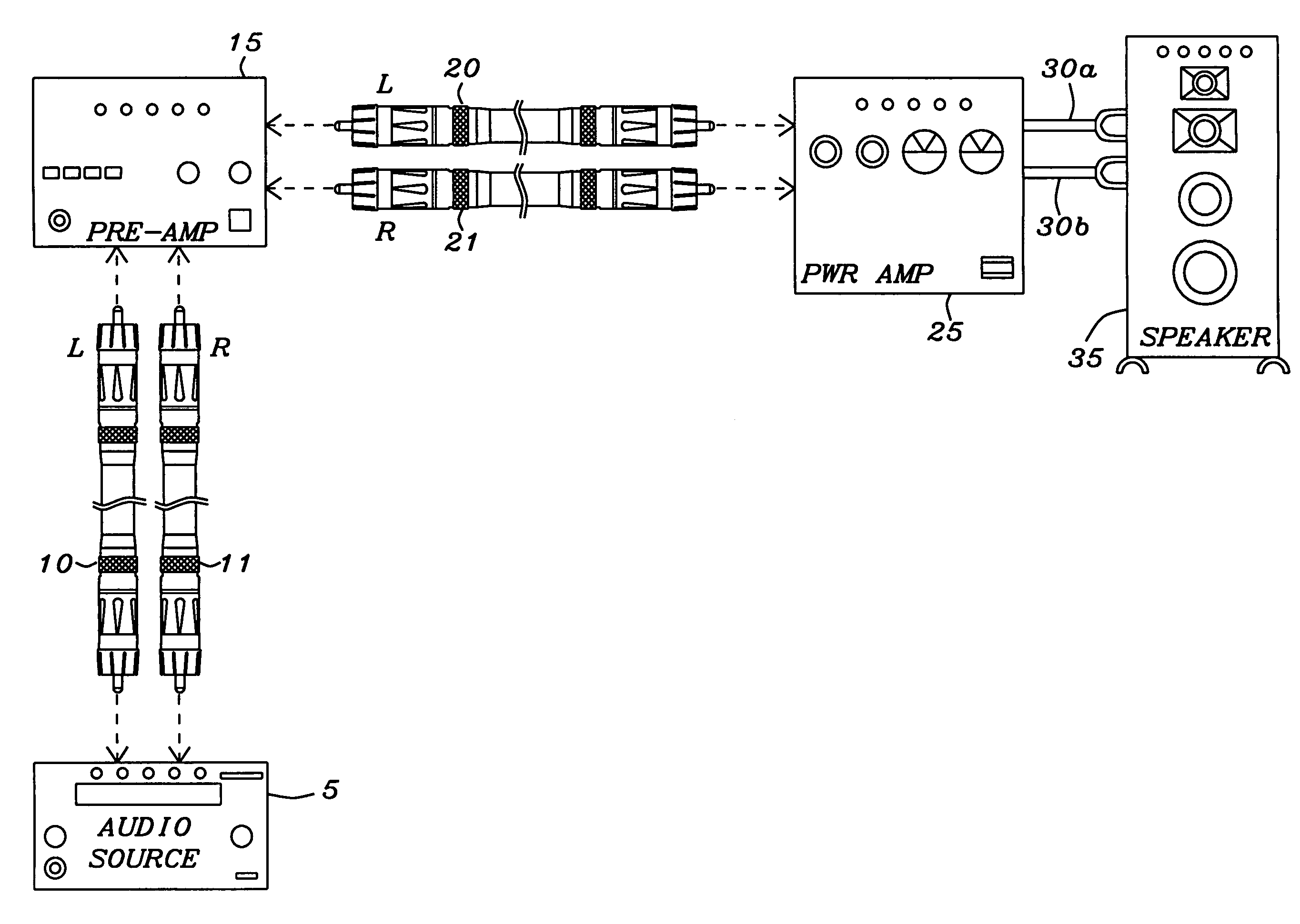
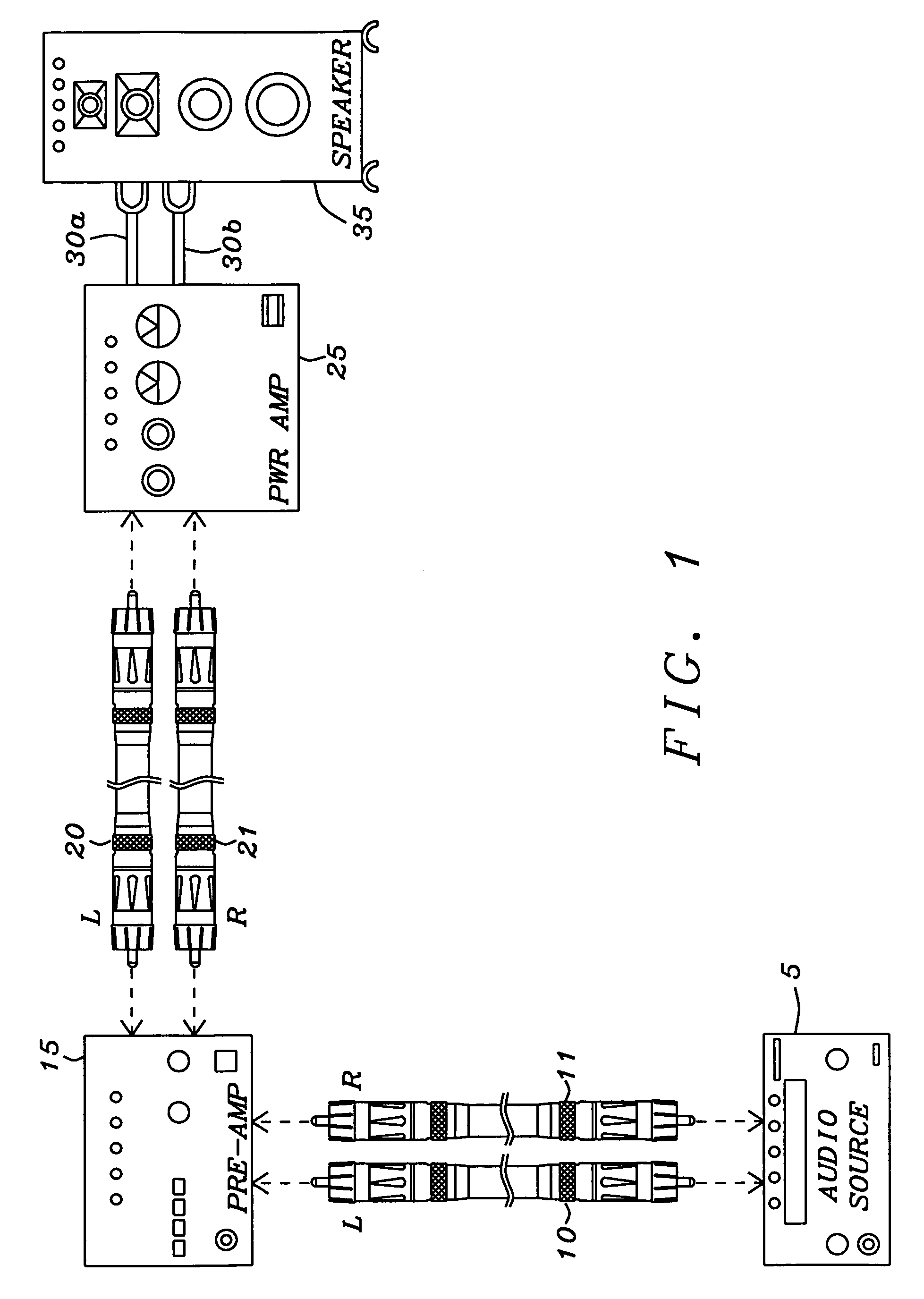
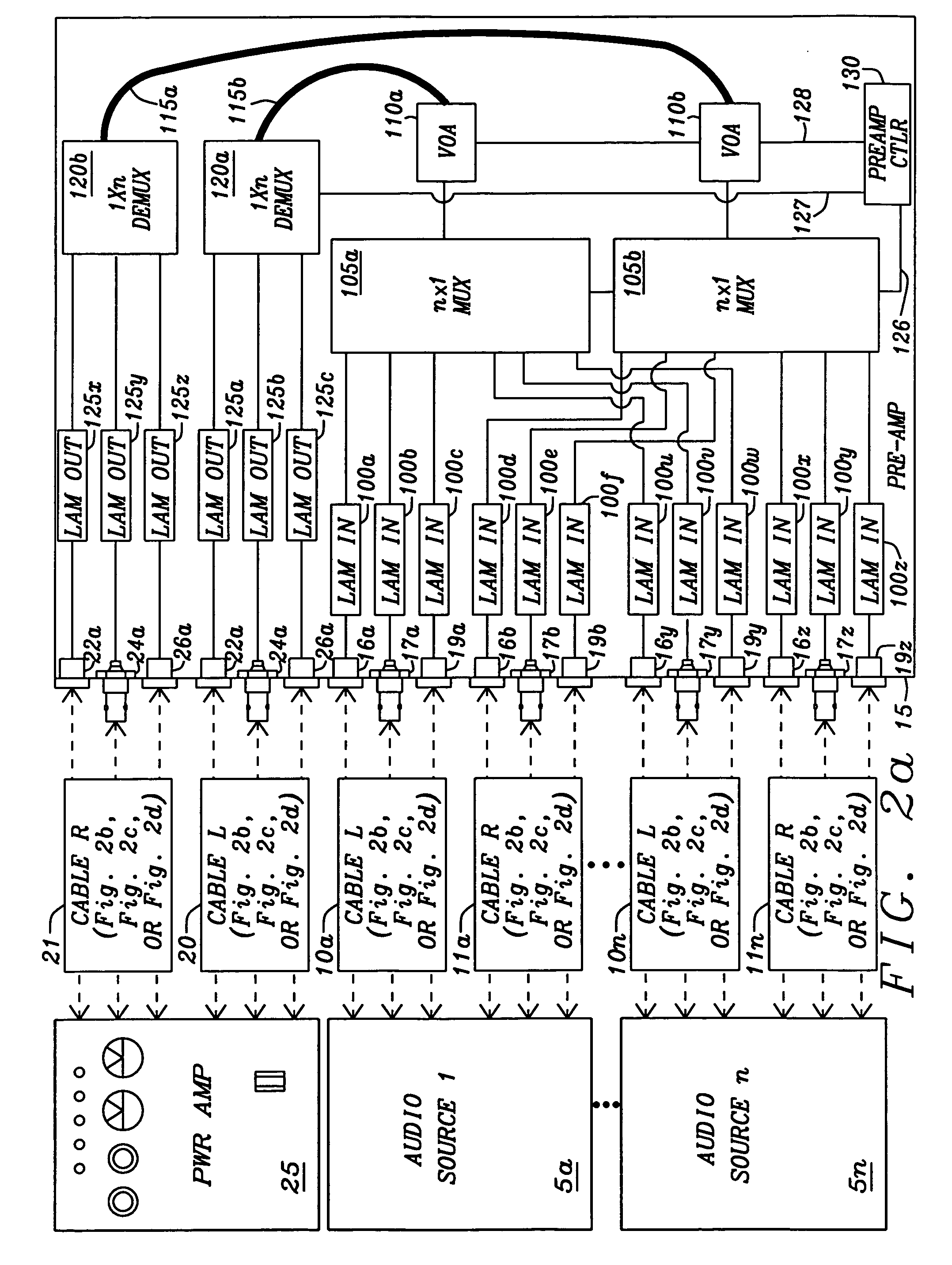
[0032]An audio system of this invention, as shown in FIG. 1, has sound generation or audio sources 5 such as compact disc, digital video disk players, microphones, and acoustic pickups or transducers on musical instruments that create low level audio signals. These audio signals are transferred through the cable assemblies 10 and 11 to the preamplifier 15. The preamplifier 15 of this invention has an electron-to-light converter to convert the low level audio signals to modulated light signals, attenuates the level of the modulated light signals to adjust the volume of the audio signals in a fiber optic volume control device and reconverts the attenuated modulated light signals to electrical signals for transfer through the cables 20 and 21. The reconverted audio signals are then transferred to the power amplifier 25 for amplification and conditioning to drive the speakers 35 through the speaker wiring 30a and 30b.

[0033]The conversion of the audio signals to modulated light signals ...


PUM


Abstract

A fiber optical audio preamplifier receives audio signals from an audio source, amplifies the audio signals, and transfers the signals to a power amplifier. The fiber optical audio preamplifier has at least one first signal converter. Each first signal converter acquires one audio signal from one audio source and converts the audio signal to a modulated light signal. At least one fiber optic volume control device that includes a variable optical attenuator that is connected to receive the modulated light signal. A control signal for sets an attenuation factor of the variable optical attenuator for attenuating the modulated light signal to control volume of the audio signal. One second signal converter is in communication with each fiber optic volume control device to receive the attenuated modulated light signal and demodulate the attenuated modulated light signal to recover the audio signal for transmission to the power amplifier.

Description

BACKGROUND OF THE INVENTION[0001]1. Field of the Invention[0002]This invention relates generally to sound reproduction systems. More particularly, this invention relates to preamplification devices that receive audio signals from sound generation sources such as compact disc players, digital video disk players, microphones, and acoustic pickups or transducers on musical instruments, amplify the audio signals for transfer to a power amplifier and then to a speaker for sound reproduction. Even more particularly, this invention relates to the preamplification of audio signals by way of an optical preamplification device.[0003]2. Description of Related Art[0004]Audio / Visual systems such as home entertainment systems or sound reproduction systems for theaters and auditoriums must transfer audio and / or video signals from sound and video generation equipment to speakers or video displays. The sound generation equipment is often connected to a preamplifier. The audio signals from the sound ...

Claims


Application Information

Patent Timeline
Patent Type & Authority Patents(United States)
IPC IPC(8): H03F99/00H01S3/00H04B10/12
CPCH03F3/087H04R27/00H04S7/30
Inventor KO, JIMMY
Owner KO JIMMY
Learn More