RO membrane cleaning method

a technology of reverse osmosis and cleaning method, which is applied in reverse osmosis, water/sludge/sewage treatment, solid sorbent liquid separation, etc. it can solve the problems of insufficient permeation and direct osmosis to reach the peripheral areas of the membrane that remains, and achieves high ionic strength, prevents membrane bio fouling, and increases salt rejection.

Active Publication Date: 2010-02-09
MEMBRANE RECOVERY
View PDF15 Cites 12 Cited by
  • Summary
  • Abstract
  • Description
  • Claims
  • Application Information

AI Technical Summary

Benefits of technology

[0031]The method where the permeate gauge pressure is raised to provide direct osmosis process has a limitation—to prevent membrane sagging in the feed direction, the gauge pressure at the permeate side must be kept significantly lower than the gauge pressure of the raw saline solution at the feed side. This requirement further limits the cleaning effect.
[0094]The present invention uses the natural osmotic pressure of a super-saline solution for membrane cleaning. Super-saline solution may be prepared from table salt with concentration below super saturation. Water produced with implementation of this invention is cleaner and healthier due to the fact that it does not include traces of aggressive cleaning reagents.

Problems solved by technology

The above-presented direct osmosis cleaning processes have a number of disadvantages stemming from some peculiarities of the osmotic processes in desalination membranes.
Due to the fact that the DO process takes place along the whole surface of every membrane in one RO module in the same time, permeate pressure is coming to vacuum and there is not enough permeate to reach peripheral areas of membrane that remains not cleaned.

Method used


Image

  • RO membrane cleaning method
  • RO membrane cleaning method
  • RO membrane cleaning method

Examples


Embodiment Construction

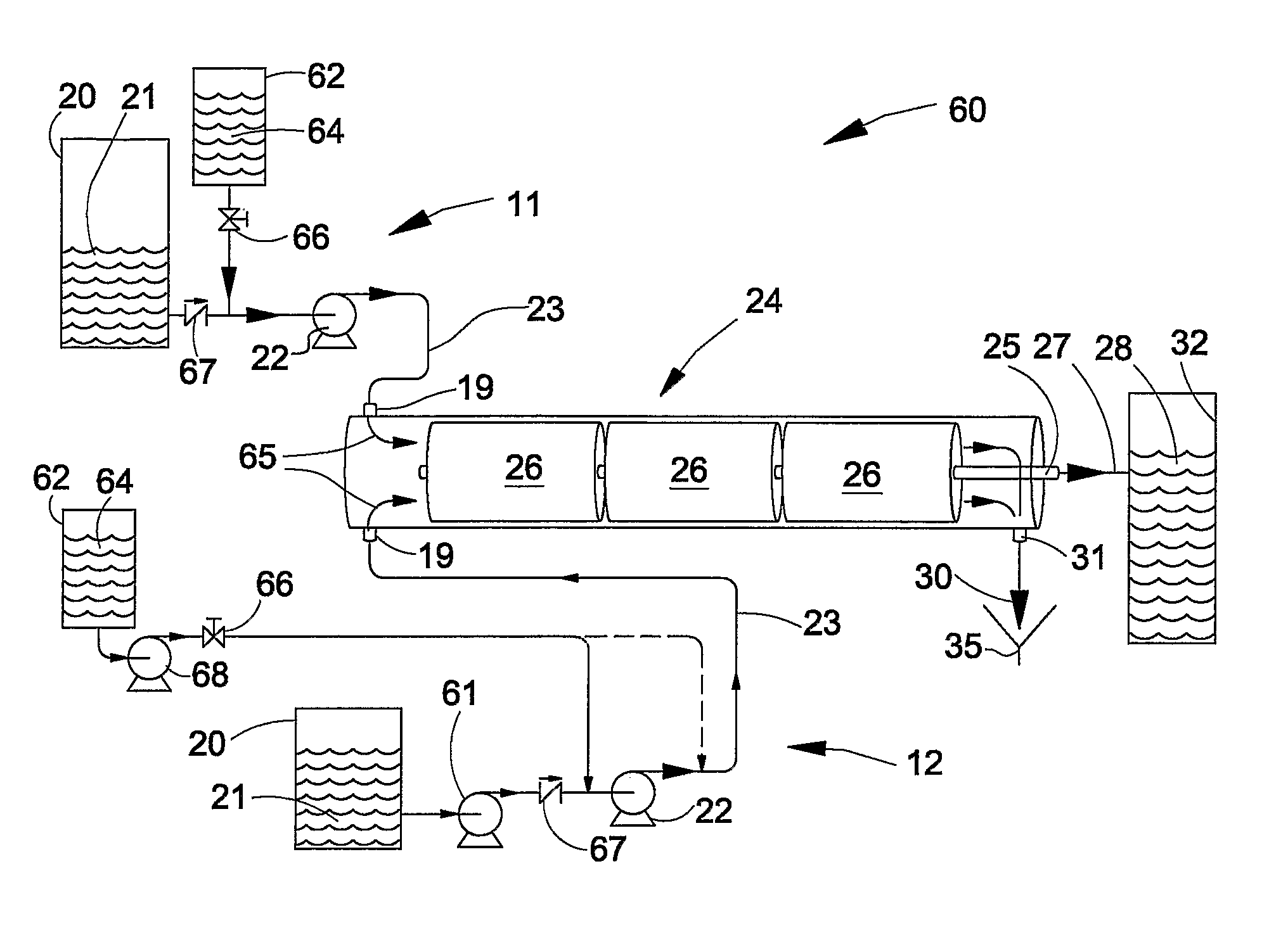
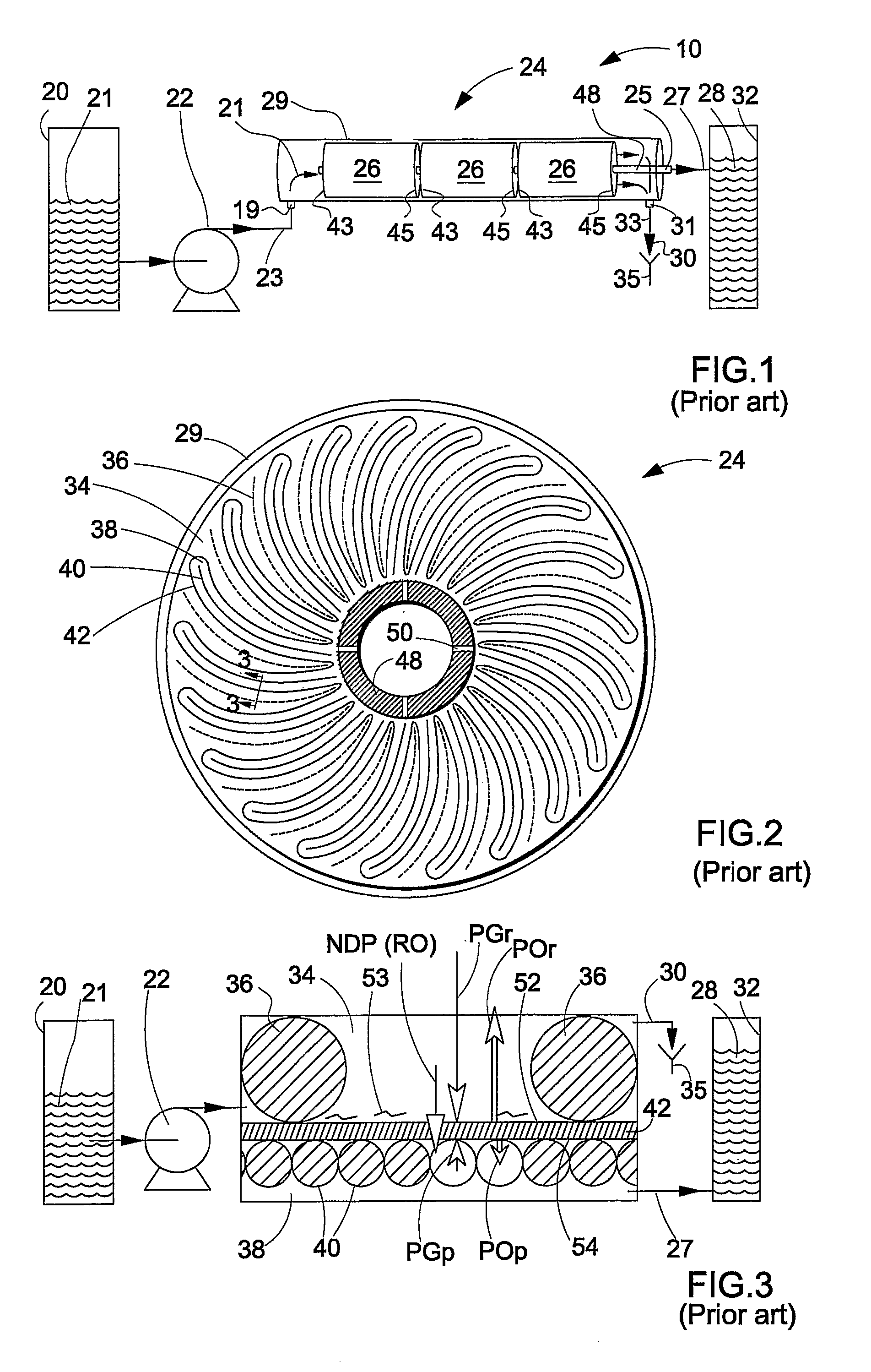
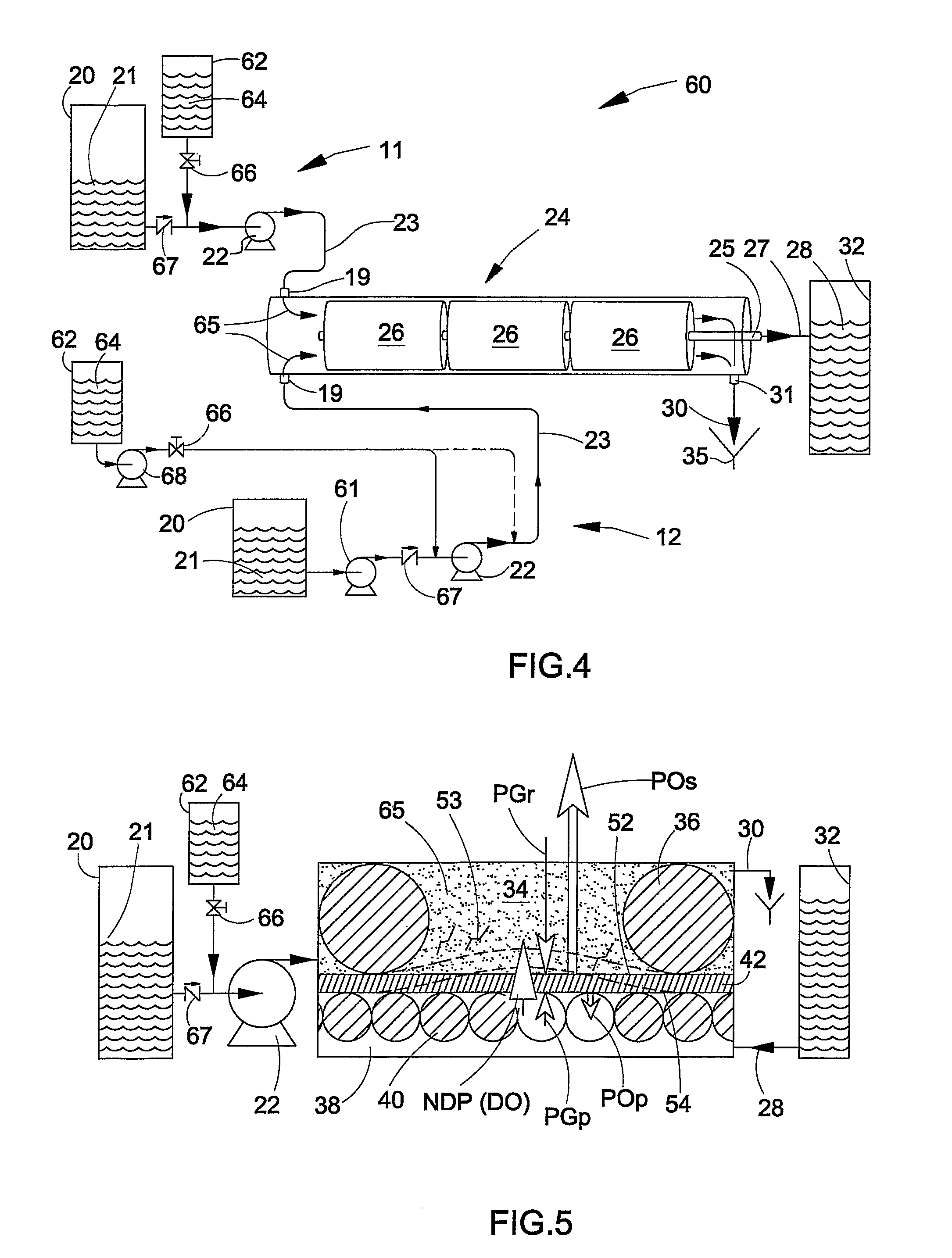
[0110]FIG. 1 shows a scheme of a RO installation 10 for water desalination comprising a raw saline solution tank 20, a high-pressure feed pump 22, a RO module 24, a permeate (product) tank 32 and a brine drain 35.

[0111]With reference also to FIG. 2, the RO module 24 has an elongated cylinder housing 29 accommodating a number of membrane elements 26, a central permeate collector 48, a feed port 19, a permeate port 25, and brine discharge port 31. Each membrane element 26 has a front end 43 facing the feed port 19 and a rear end 45 facing the brine port 31. The membrane elements 26 are arranged in series on the permeate collector 48.

[0112]A schematic cross-section of the RO module 24 and a membrane element 26 is shown in FIG. 2. The membrane element 26 comprises a plurality of membrane sheets (membranes) 42 spirally folded around the permeate collector 48. Outer folds of the membrane sheets are separated by raw water spacers 36 and together with the housing 29 define feed-brine channe...


PUM

PropertyMeasurementUnit
pressureaaaaaaaaaa
pressureaaaaaaaaaa
osmotic pressureaaaaaaaaaa

Abstract

Direct-osmosis (DO) method for cleaning a semi-permeable membrane in a RO separation module, the membrane having a feed side with foulant located thereon, and an opposite permeate side. A normal RO separation process in the same module includes: feeding, under gauge pressure PGr, raw saline solution having osmotic pressure POr to the membrane feed side; collecting permeate (solvent) having osmotic pressure POp from the permeate side, under gauge pressure PGp; and removing residual brine from the membrane feed side. The method comprises feeding to the feed side of the membrane, for a predetermined injection time, super saline solution having osmotic pressure POs>POr, such that backward flow of permeate towards the feed side of the membrane is provided so as to lift the foulant from the feed side.

Description

[0001]This is a National Phase Application filed under 35 U.S.C. 371 as a national stage of PCT / IL2005 / 000514 filed on May 19, 2005, an application claiming the benefit under 35 USC 119(e) U.S. Provisional Application No. 60 / 580,915 filed on Jun. 21, 2004, the content of each of which is hereby incorporated by reference in its entirety.FIELD OF THE INVENTION[0002]This invention relates to cleaning of reverse osmosis (RO) membranes such as used in sea and brackish water desalination technology, for municipal and industrial water production, in particular to cleaning by direct osmosis.BACKGROUND OF THE INVENTION[0003]The process of reverse osmosis (RO) desalination of raw water includes basically the following:[0004]providing a semi-permeable membrane (RO membrane) which allows passing of the solvent (water) molecules and rejects dissolved salts, and disposing the RO membrane in a suitable vessel;[0005]feeding the raw water to one side of the RO membrane (“feed” side) under gauge pres...

Claims


Application Information

Patent Timeline
Patent Type & Authority Patents(United States)
IPC IPC(8): B01D65/02B01D61/10B01D63/12B01D65/06C02F1/44
CPCB01D61/025B01D61/10B01D63/12B01D65/02B01D67/0081C02F1/441B01D2321/04B01D2321/06B01D2321/168B01D2321/2083B01D2323/42C02F2103/08Y02A20/131
Inventor LIBERMAN, IGAL
Owner MEMBRANE RECOVERY
Why Eureka
Try Eureka